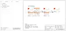
EV-Charger Function
The inverter can communicate with the smart EV-Charger to form an
intelligent photovoltaic, storage and EV charging energy system, thus
maximizing the utilization of photovoltaic energy.
Electrical
grid
PV array
AC distribution box
Inverter
Electricity meter,
bidirectional
Meter
Mode Select
Meter
Export Control
DRM Function
Diagram: Intelligent Photovoltaic, Storage and EV Charging Energy System
Mode Select
CT
·
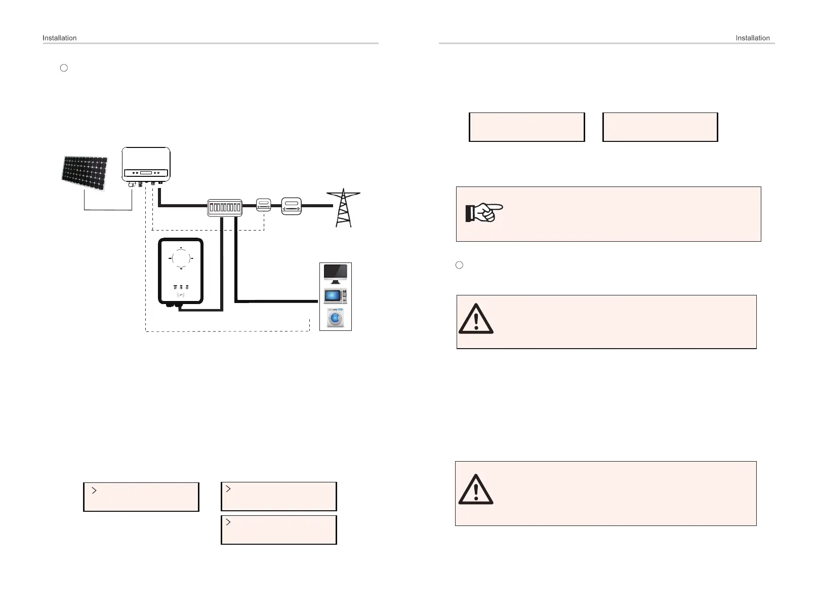
Wiring operation
a) Plug one terminal of the communication cable to the right pin of the EV-
Charger and the other terminal to PIN 4 & 5 of the "COM/CT" port of the
inverter.
b) Connect the meter to PIN 4 & 5 of the "COM/CT" port of the inverter.
Setting
Turn on the power of the entire system, enter the "Settings" page of the
inverters on the LCD screen.
a) Enter the "Export Control" page and chose "CT" or "Meter".
46
47
Load
>EvChargerEnable
Adapter Box
>Mode Select
Enable
b) Select “EvChargerEnable” and then enter "Mode Select". Ensure the
interface shows "Enable" under "Mode Select", which indicates the EV-
Charger function started successfully.
For the installation and settings of the EV-Charger, please refer to the user
manual of the EV-Charger for details.
Note!
The EV-Charger function and the parallel system with
Datahub or the parallel system with Modbus Function
cannot be used at the same time currently.
Upgrade
User can update the inverter system through the USB flash dirver.
4
WARNING!
Make sure the input voltage is more than 100 V dc (in good
illumination condition), otherwise it may result in failing
during updating.
Upgrade Steps:
Ø
1) Please contact our service support to get the update file, and extract it into
your USB flash dirver as the following file path:
“Update\ARM\323101023800_X1_MINI_G4_ARM_VXXX.XX_XXXXXXXX.bin”;
“Update\DSP\323101023700_X1_MINI_G4_DSP_VXXX.XX_XXXXXXXX.bin”.
Note: Vx.xx is version number, xxxxxxxx is file completion date.
WARNING!
Make sure the directory is in accordance with above form
strictly!
Do not modify the program file name! Otherwise it may
cause the inverter not to work anymore!
3

 Loading...