Wiring Diagrams
9
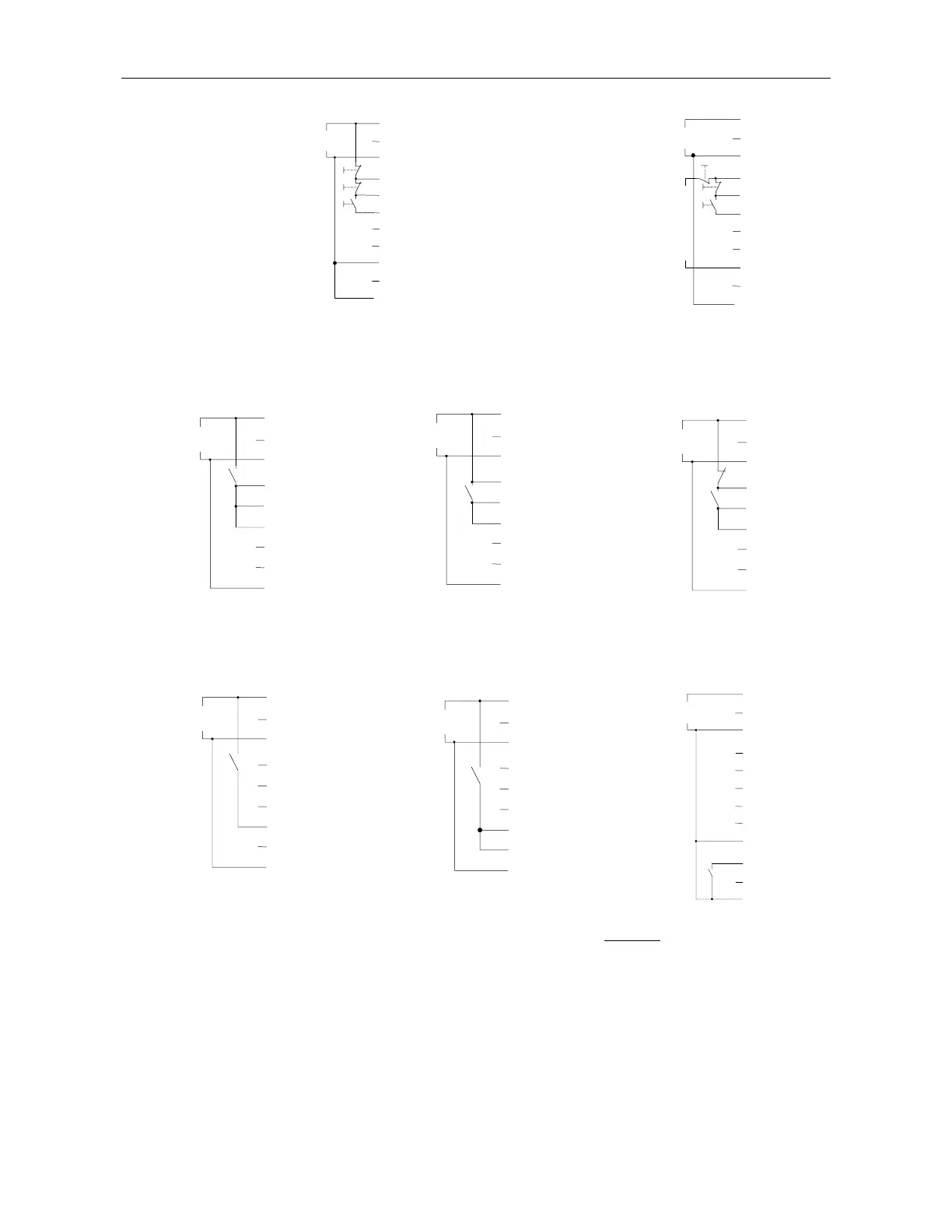
1. Start, soft stop and stop
buttons, single supply
source for Control Supply
and Control Inputs.
If Soft Stop is not used,
connect a jumper between
terminals 4-5 connect
emergency stop and /or
soft stop between
terminals 1-4.
2. Start-Stop push
buttons, Separate
sources for Control
Supply and Control
Inputs.
If Soft Stop is not
used, connect a
jumper between
terminals 4-5.
3. Motor will soft start
when C closes and stops
immediately when C opens.
4. Motors will soft start
when C closes and soft stop
when C opens
5. Motors will soft start and
soft stop with C. C1 act as
emergency stop.
6. Close C to operate
Energy Save, Slow speed or
Reset – as selected.
7. Close C to operate Dual Adjust.
Slow Speed Reversing or Reset –
as selected.
8. External Fault contact.
The starter will trip 2 sec after C
closes.
C must be of momentary type when
used as Reset
For Slow speed reversing terminal 7
must be connected to Control Supply
Must Not
be used when 21 is not
connected to neutral/ground or when
Insulation Test is used
Notes: 1. Terminal 21 may be connected to terminal 3 only if terminal 3 is at neutral or at ground potential.
2. Resetting is possible only after start signal is removed
1
2
3
4
5
6
7
8
9
21
19
20
L
1
N
C
1
2
3
4
5
6
7
8
9
L
1
N
C
*
1
2
3
4
5
6
7
8
9
L
1
N
C
*
1
2
3
4
5
6
7
8
9
L
1
N
C
C
1
1
2
3
4
5
6
7
8
9
L
1
N
C
1
2
3
4
5
6
7
8
9
L
1
N
C
Soft Stop
1
2
3
4
5
6
7
8
9
L
1
N
Stop
Start
21
1
2
3
4
5
6
7
8
9
L
1
N
Stop
Soft Stop
Start
21