By-pass Contactor
3
Under normal operating conditions, the heat dissipated
by an electronic soft starter causes heating of the
enclosure and energy losses. The heating and losses
can be eliminated by the use of a by-pass contactor,
which by passes the RVS-DN after completion of start-
up, so motor current will flow through the by-pass
contactor.
In this case the starter protection
will be maintained except for the
current protection, as the current
will not flow through the internal
current transformers after the by-
pass closes.
Preparation for By-pass Contactor (option)
In order to maintain current protection after the by-pass
contactor closes, Preparations for By-pass Contactor
can be ordered.
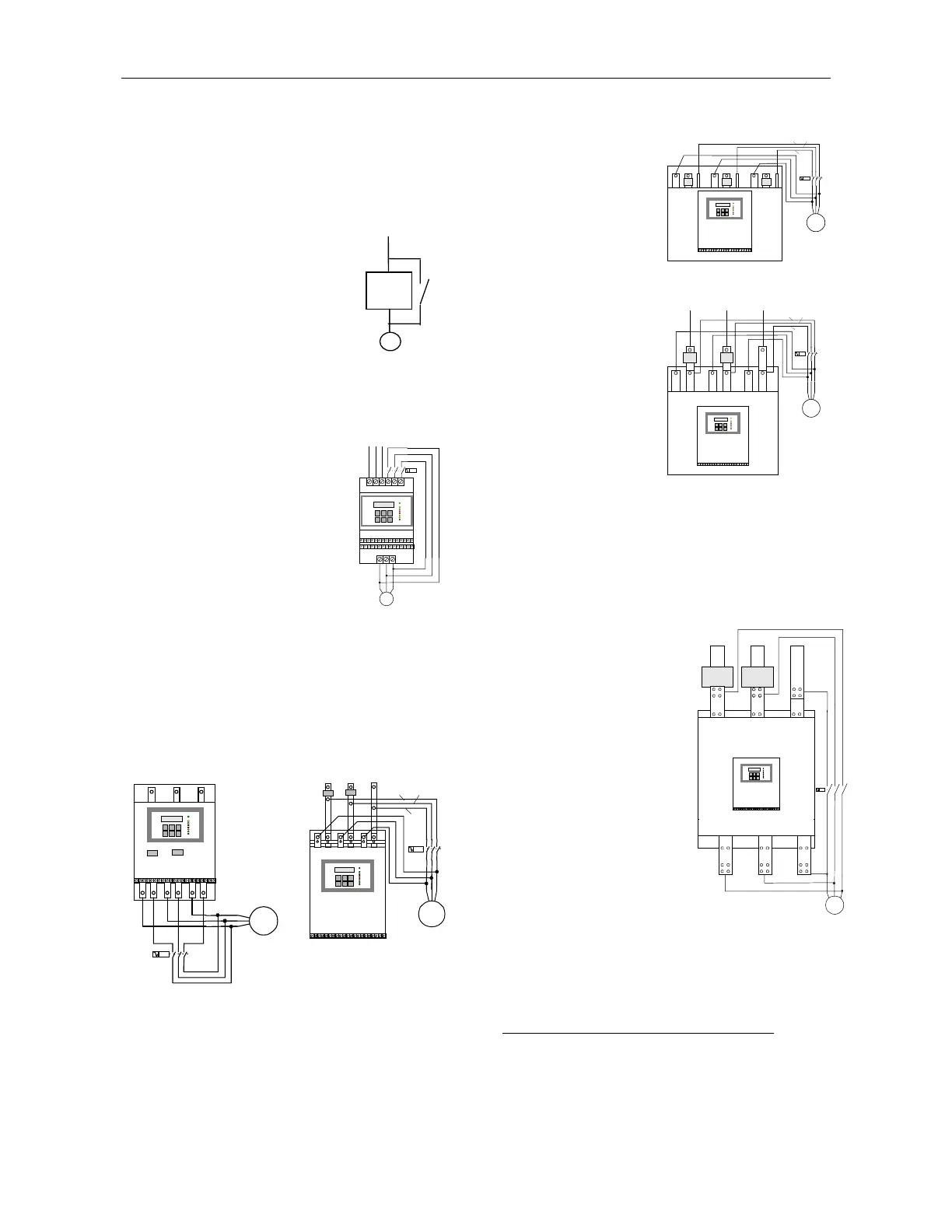
Frame Size A (8 – 72A)
Must be factory supplied, three
additional terminals are added,
marked L
1b
, L
2b
, L
3b
.These
terminals are connected after the
internal C/Ts, intended for
connection to the by-pass.
UVW
L1
b
L2
b
L3
b
L3L1 L2
Frame Sizes B (Standard and New 85-170A)
Old – Additional set of bus-bars can be field mounted
on the line side, after the C/Ts, marked L
1b
, L
2b
, L
3b
.
New – Additional set of bus bars is built-in, where the
line side is on top and motor side is at the bottom with
the by-pass
L
1b
, L
2b
, L
3b
terminals are located. By-pass contactor
cables should be connected to these terminals.
L1
b
L2
b
L3
b
L3L1 L2
UVW
Built in
M
L1
b
L2
b
L3
b
L3L1 L2
M
C/T
U V W
Frame Size C
(210 - 390A)
Additional set of bus
bars can be field
mounted on line side,
after the C/T’s marked
L
1b
, L
2b
, L
3b
. Bypass
cables should be
connected to these
terminals.
L2b
L3b
M
L1b
U L1 V L2 W L3
Frame Size D
(460 - 820A)
Additional set of bus
bars can be field
mounted on line side,
downstream to the
C/T’s marked L
1b
, L
2b
,
L
3b
. Bypass cables
should be connected to
these bus-bars.
L2b
L3b
M
L1b
U V W
L3L1 L2
C/T C/T
Note: Starter frame sizes C and D can be field modified
to have Line and Load Bus-bars at the bottom (consult
factory for further information).
Frame Size E
(1100 – 1800A)
Frame Size F
(2150A)
Frame Size G
(2400 – 3500A)
Additional set of bus-bars
can be field mounted on line
side, down stream to the
C/Ts, marked L
1b
, L
2b
, L
3b
.
By-pass cables should be
connected to the bus-bars
down stream to the C/T’s
Note: Connect as follows
• Line to L1, L2, L3
• By-pass
Input to L
1b
, L
2b
, L
3b
Output to U, V, W
• Motor (Load) to U,V,&
W
C/T
L1
M
U V W
L1b L2b L3b
C/T
L2 L3
Do not interchange line and load connections.
M
By Pass
Contactor
RVS-DN