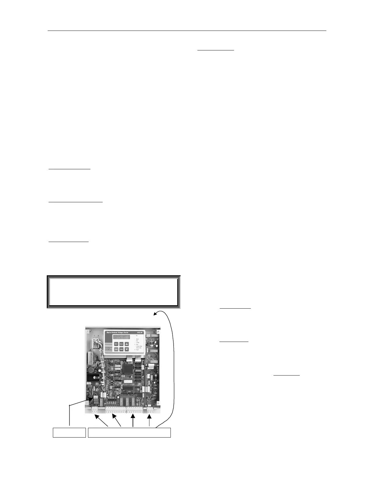
Control Terminals
4
Control Supply Terminals 1-3
110-120VAC or 220-240VAC, 50/60Hz as indicated
on the front panel, required to power the electronic
circuitry and fans when incorporated. This voltage can
be from a grounded or ungrounded main system.
110VDC can be supplied by special order for starter
sizes B-G (not field interchangeable).
Note: It is recommended that terminals 1-3 be
always connected to the Control Supply.
Fan’s Supply Voltage Terminal 2
An internal jumper, connected between fan and
terminal 2 enables three modes of operation (see Fan
Control – page 16). For fan power consumption, see
technical specification.
Continuous mode
(factory default) – Fan operates as
long as Control Supply is connected to terminals 1-3.
Leave internal jumper connected to left lug of JI
terminal (A).
External control mode
– Fan operates when Control
Supply is connected to terminal 2. Connect internal
jumper to the center lug of JI terminal (B). For use
without by-pass, connect fans before “start” and
disconnect at least 5 minutes after “Stop/Soft-stop”.
Automatic mode
– Fan begins operation when start
signal is initiated and stops approximately five minutes
after start signal. When stop signal is initiated, the fan
begins operation and stops after five minutes. Connect
internal jumper right lug of JI terminal (C).
WARNING
Automatic mode may be used only if by-pass
contactor is directly controlled by the RVS-DN “End-
of-Acceleration” contact.
1-3 4-9 10-21 22-24 25-32
I/O Terminals
Internal Fan
Terminals
Control Inputs
Incorporating opto-couplers to isolate the micro-
processor circuitry.
The starter is supplied standard for 220-240V, 50/60Hz
Control Supply and Control Inputs voltage.
By special order, Control Inputs may be supplied for
voltage levels of 24-240 VAC/DC. (for more
information, see Ordering Information data – Appendix
page 48).
Stop Terminal 4
Input from a N.C contact. To stop the motor,
disconnect control voltage from Terminal 4 for at least
250mSec.
Soft stop Terminal 5
Input from a N.C contact. To soft stop the motor,
disconnect control voltage from Terminal 5 for at least
250mSecs.
Note: If Soft Stop is not required, connect a
jumper between terminals 4 and 5.
Start Terminal 6
Input from a N.O contact. To start the motor, connect
control voltage to Terminal 6 for at least 250mSecs.
Notes:
1. Motor will start only if Stop (4) and Soft Stop
(5) terminals are connected to control voltage.
2. Reset after a fault is not possible for as
long as Start command is present.
Energy Save / Slow Speed / Reset Terminal 7
Input from a N.O contact. Selection between above
functions is made from the keypad or through the
communication (see I/O Programm.)
• When Energy Save
function is selected –connect
terminal 7 to control voltage by a jumper for
automatic operation, upon load decrease.
When connected through a N.O contact, closing the
contact operates Energy Save.
• When Slow Speed
function is selected – connect
control voltage to terminal 7 before starting, to run
the motor at 1/6 nominal speed. Closing terminal 7
while motor is running will not have any effect.
• When Reset function is selected, connect terminal 7
to control voltage (use a N.O momentary
contact) to
reset the starter.