7
Control Terminals – Option Boards
Option # 3
RS-485 Communication Terminals 23-24
Terminals: 23 (-), 24 (+)
Standard RS485, Half Duplex with MODBUS
Protocol, baud rate 1200, 2400, 4800, 9600 BPS.
Twisted shielded pair should be used, connect shield to
ground a PLC/Computer side. Terminals 4 & 5 must be
wired to control supply for operation in communication
mode (see Wiring Diagram – page 14 and
Communication Instruction Manual).
Option # 4
Insulation Alarm Terminals 25-26-27
Terminals: 25- Common 26- N.O. 27 – N.C.
Voltage free 8A, 250VAC, 2000VA max. changes its
position when motor insulation level decreases below
Insulation Alarm level. The contact returns to its
original position, after fault has been removed and
starter reset, or upon Control Supply disconnection, or
when insulation level increase above Alarm set-point
for more than 60 sec.
Notes:
1. Do not use External Fault while using
Insulation Alarm option.
2. Insulation test can be performed only when
main voltage is not connected to the RVS-DN,
namely an upstream isolation device must be
opened.
For correct operation of Insulation test, it is
important that the RVS-DN is properly
grounded and that the control module is
properly fastened to the power section.
3. Option # 4 and option # 5 may not be applied
together.
Option # 5
Analogue I/O (option # 5) Terminals 28-32
The Analogue card output
incorporates two functions:
• Thermistor input
• Analogue output
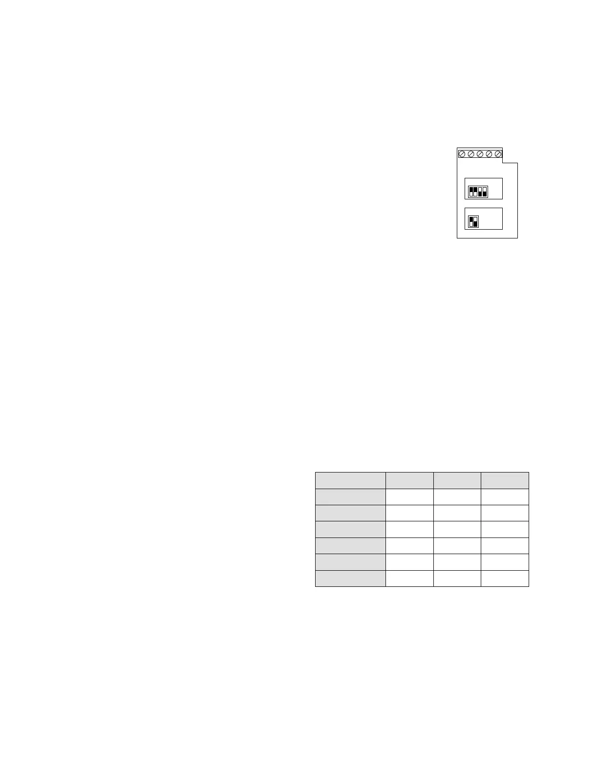
Analogue P.C.B. layout:
Dip. Sw. S1
Off
Dip. Sw. S2
Off
32 31 30 29 28
Out (+)
Out (-)
Ground
T2
T1
Thermistor input Terminals 28-29
Programmable as PTC or NTC type thermistor. Trip
value is adjustable between 1-10K, preset delay of 2
Sec.
Ground Terminal Terminal 30
Connect thermistor and / or Analogue output shield to
this ground terminal.
Analogue Output Terminals 31, 32
Terminal: 31 (-), 32(+)
Dip switches allow selection between: 0-10VDC
0-20mA
4-20mA
Analogue value is related to motor current and can be
programmed to normal or inverted output. (Default =
Normal) Maximum value (20mA or 10Vdc) is related
to twice the RVS-DN rated current (2xFLC).
Dip No. 4-20 mA* 0-20 mA 0-10VDC
Dip-Sw. S1 # 1 On On Off
Dip-Sw. S1 # 2 On On Off
Dip-Sw. S1 # 3 Off Off On
Dip-Sw. S1 # 4 Off Off On
Dip-Sw. S2 # 1 On Off Off
Dip-Sw. S2 # 2 No use No use No use
* Default
Notes:
1. It is important that the RVS-DN is properly
grounded, and control module is tightly fastened to the
power section.
2. Option # 5 and option # 4 may not be applied
together.
3. Use twisted shielded cable for thermistor connection.