Wiring Diagrams - Communication
13
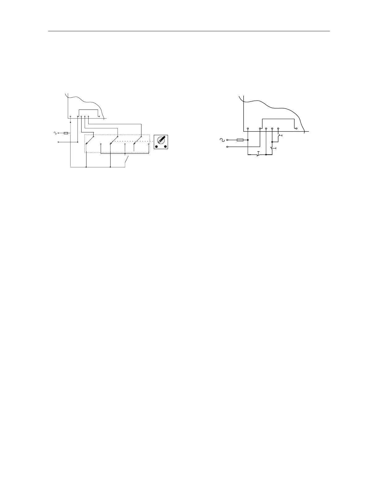
Operation via communication link with
Local/Remote (selector switch)
• Remote: via Communication link
• Local: Soft-start, immediate-stop by
maintaining contact.
1 3 4 5 6 9
N
Start
Stop
Remote
Local
Soft-start and immediate stop
Same as the explanation for
Soft-start
and
soft stop
,
except for # 4:
4. During operation via communication link,
terminals 4 and 5 are connected through the
Local / Remote selector switch to Control
Supply and Start-Stop commands are
controlled through the communication port.
During operation in Local mode, terminals 4,
5 and 6 are connected to Control Supply
through the Start-Stop toggle switch.
Operation via communication link with Momentary
contact (Push-Buttons) Soft-start, immediate stop,
soft-stop.
1 3 4 5 6 9
Start
Soft Stop
N
Immediate
Stop
Soft-start, Soft-stop and immediate stop
Same as the explanation for
Soft-start
and
soft-stop
,
except for # 2 and # 4:
2. Connect terminal 4 as described below.
4. During operation via communication link,
terminals 4 and 5 are connected through the
push buttons to Control Supply and Start-Stop
commands are controlled through the
communication port.
During normal operation mode, terminals 4 and
5 are connected to Control Supply through the
Immediate-stop and soft-stop push buttons, soft-
start command may be initiated by pressing the
start push-button.
Notes:
The communication (data retrieval and statistics) is active at all times!
When control signals (start, stop, etc.) are required, terminals 4 and 5 have to be wired in
accordance with the appropriate wiring diagram:
1. Maintained soft-start and stop
2. Maintained soft-start with immediate stop.
3. Soft-start/stop with immediate stop via push-button control.