Start & Stop Parameters
19
Maximum Start Time
The maximum allowable starts time, from start signal
to end of acceleration. If voltage does not reach full
voltage during this time (for example, because of low
Current Limit setting), the starter will trip the motor.
LCD displays “Long Start Time” message.
Range: 1-30 sec (consult factory for extended range).
Contact Delay
Time delay for End of Acceleration Contact, after
completion of starting process. Range: 0-120 sec.
Pump Control – Stop curve
Intended to prevent Water Hammer during stopping. In
pump applications, load torque decreases in square
relation to the speed, thus, reducing the voltage will
reduce torque and motor will smoothly decelerate to a
stop.
The following Stop curves can be selected:
Stop curves 0 – Standard Default curve – voltage is
linearly reduced from nominal to zero.
Stop curves 1, 2, 3 –
In some pump
applications, when
pumping to a higher
level, a considerable
part of the torque is
constant and does
not decrease with
speed. It may happen
that during Soft Stop, when voltage is decreasing,
motor torque quickly falls below load torque and motor
will abruptly stall instead of smoothly decreasing speed
to zero.
Stop Curve 4 (Torque) –
Provides Linear Controlled
torque deceleration ramp,
from Ta (Actual Torque),
thus, eliminating stall
conditions.
Note:
Always use Stop Curve 0. If motor stalls
quickly instead of slowly decreasing its speed,
select Stop Curve 1, 2, 3 or 4 if necessary.
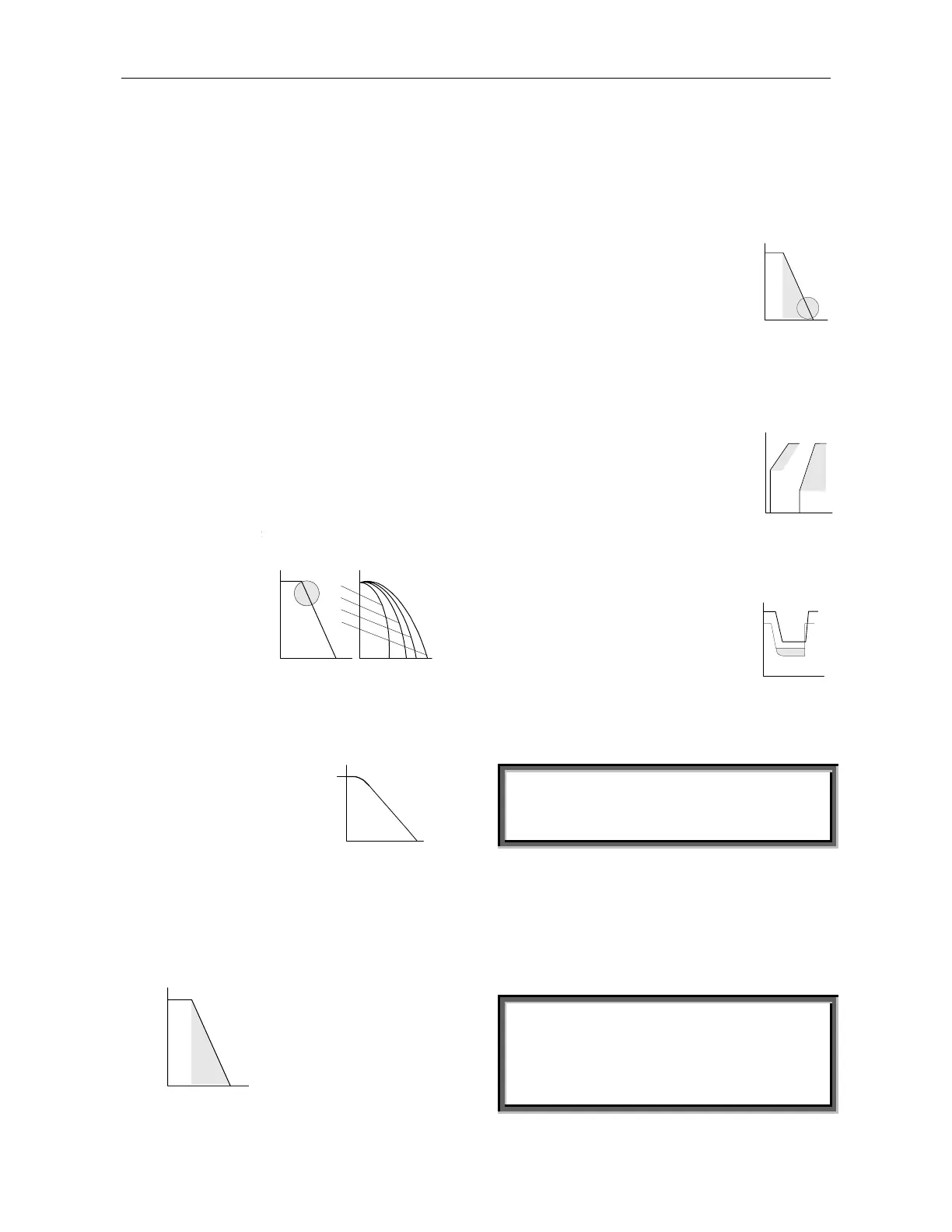
Deceleration Time – Soft Stop
U%
2
100%
30sec
Used for controlled
deceleration of high friction
loads. Determines motor’s
voltage ramp down time.
Range: 1-30 sec. (consult
factory for extended range).
Note: When the starter operates with a by-pass
contactor, Soft Stop initiation opens the End Of
Acceleration contact, tripping open the by-pass
contactor. Load will then be transferred to the RVS-
DN and voltage begins ramping down.
Final Torque
Determines torque towards end of
Soft Stop. If current is still flowing
after speed is softly reduced to zero,
increase Final Torque setting.
U%
2
100%
30 sec
Dual Adjustment
A secondary set of parameters, used for varying loads,
two speed motors, etc. Connecting Control Supply to
Terminal 8 makes transfer to Dual Adjustment settings.
IV - Initial Voltage 10-50% of Un.
CL - Current Limit 100-400%
of motor’s FLA
AT - Acceleration Time 1-30 sec.
DT - Deceleration Time 1-30 sec.
FLA- Motor Full Load Ampere.
U%
100%
sec
2- -302- -10
40%
100%
20%
Note: Consult factory for extended range.
Energy Save
Activated when motor is lightly
loaded for extended periods of time.
Supply voltage the motor decreases
(lowering the rotating magnetic
field intensity), thus, reducing the
reactive current and copper/iron
losses.
U Starter
In
Un
0.5
I Motor
Note: When using Energy Save system, harmonics
should be taken into consideration. At maximum
Energy Save settings, the 5
th
harmonic may exceed
30% of the RMS current value.
ATTENTION
To meet CE standards while in Energy Save mode,
the user may be required to employ additional
mitigation methods.
Slow Speed Torque
Determines the torque while motor is operating at 1/6
of nominal speed. Range: 1-10.
Maximum Slow Speed Time
Determines the maximum allowable operation time at
slow speed. Range: 1-30 sec. (consult factory for
extended range).
WARNING
Operating current while motor is running at 1/6 speed
is much higher than nominal current and motor
ventilation is much weaker. Special precaution must
be taken to prevent overheating when running the
motor at slow speed for long periods of time.
urves 1, 2, 3 designed to prevent
tall condition
Voltage Deceleration
1!!
0
2!!
3!!
t
Torque
Ta
Time > t1
Increased time
smoothes the Peak