Pump Control
32
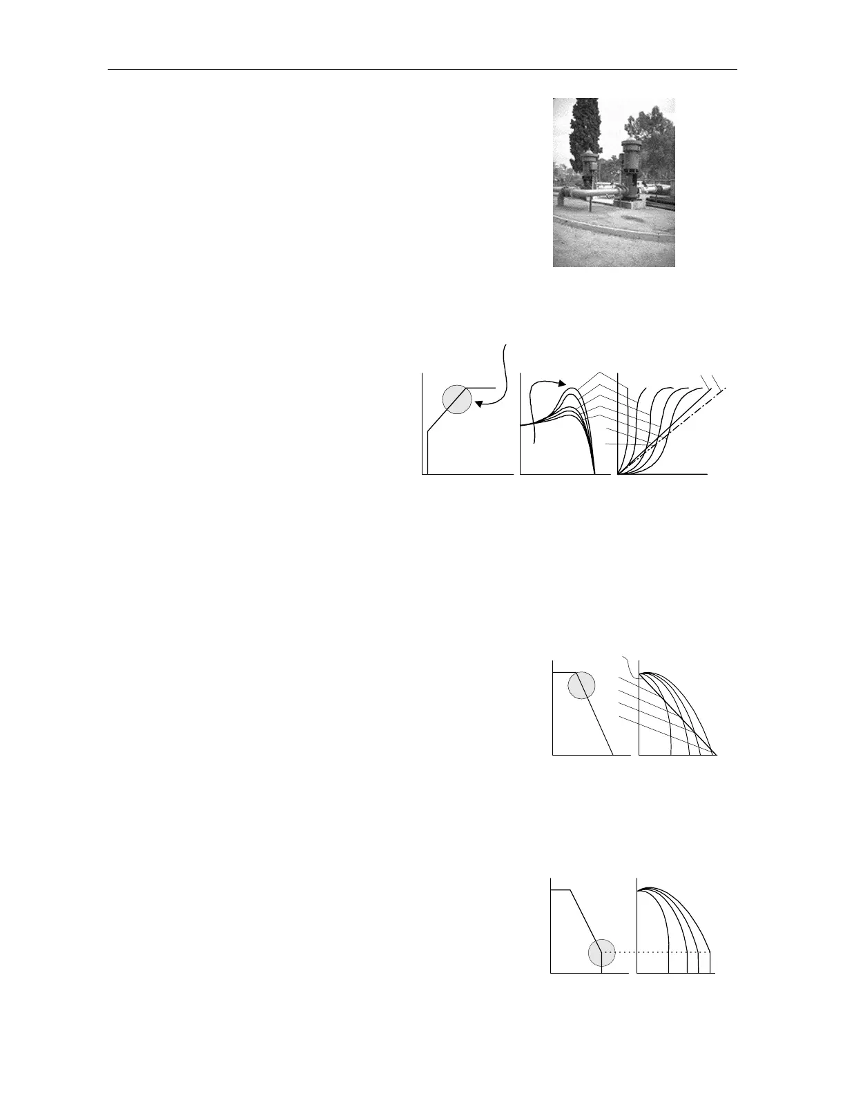
Choosing a suitable Pump Curve (centrifugal Pumps)
Starting Curve
1. Adjust main parameters as necessary (FLA, FLC, etc..)
2. Set Starting Curve, Acceleration Time, Current Limit, and Initial
Voltage to their default values (curve 0, 10 sec., 400% and 30%
respectively).
3. Start the pump while watching the pressure gauge as the pump starts
and look for overshooting (“Pressure Surge”) of the gauge needle
above the target pressure. In case of over pressure, choose a peak
torque reduction curve (Pump Control curve 1!).
4. Set Start Curve 1!, increase Acceleration Time
to 15 sec. and reduce Current Limit to 350%.
Start the pump and watch the pressure gauge
while the pump starts.
5. In most cases, overshooting is reduced, if the
overshoot persists, increase Acceleration time to
25 sec. (confirm with motor manufacturer) and
try again.
6. If the overpressure persists, increase Starting
Curve setting to 2!, 3!, 4 (Torque) or 5 (Current
Ramp) if necessary. Each increase in Starting
Curve setting will reduce the Peak Torque, thus,
reducing the overpressure and preventing the
“Pressure Surge” during start.
7. To increase starting time above these
maximums, employ “Special Starting” (page
32) with these techniques or incorporate Torque
and Current characteristics.
Pump control during
operating area
Speed
Sec
TorqueVoltagae
DOL
0
1
2
3
Peak
Torque
4
5
4 5
Stopping Curve
1. Adjust main parameters as necessary (FLA, FLC, etc..)
2. Set Stop Curve and Deceleration Time, to their default values (curve
0, 10 sec., respectively).
3. Stop the pump, watching the pressure gauge and the check valve as
the pump stops. Look for undershooting/overshooting (“Water
Hammer”) of the gauge (which may abruptly stops the pump and the
motor).
4. Select Stop Curve 1, increase Deceleration time to 15 seconds. Stop
the pump and watch the pressure gauge and the rate of closing of the
check valve as the pump stops. Abrupt stopping of the pump and motor
will cause a loud audible noise emitted from the check valve.
5. In most cases, “Water Hammer” is reduced. If the “Water Hammer”
persists, increase the time to 25 seconds (confirm with motor
manufacturer) and try again.
6. If the “Water Hammer” persists, increase Stop Curve setting to 2!, or
3!. Each increase in stop curve will reduce the abrupt stop of the pump,
thus, preventing the “Water Hammer” phenomenon.
7. If the extent of the water hammer was not reduced, increase to stop
curve # 4 to employ Torque Controlled deceleration.
Voltage Deceleration
1
0
2
3
4
Final torque during soft-stopping a pump motor
1. While decelerating, the check valve may close before Deceleration
Time has elapsed, thus, allowing current to flow through stator winding
causing unnecessary heat. Select Final Torque sensitivity to 1, and stop
the pump, confirm that current stopped flowing through the motor
shortly after the check valve closed.
2. If current still flows more than 3-5 seconds after check valve closure,
increase Final Torque up to 10 if necessary, to stop current flow earlier.
Voltage Deceleration
SecFT1
FT10