ORIGIN Installation Guide
Making Connections
19
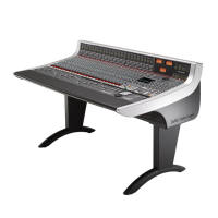
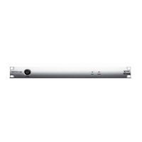
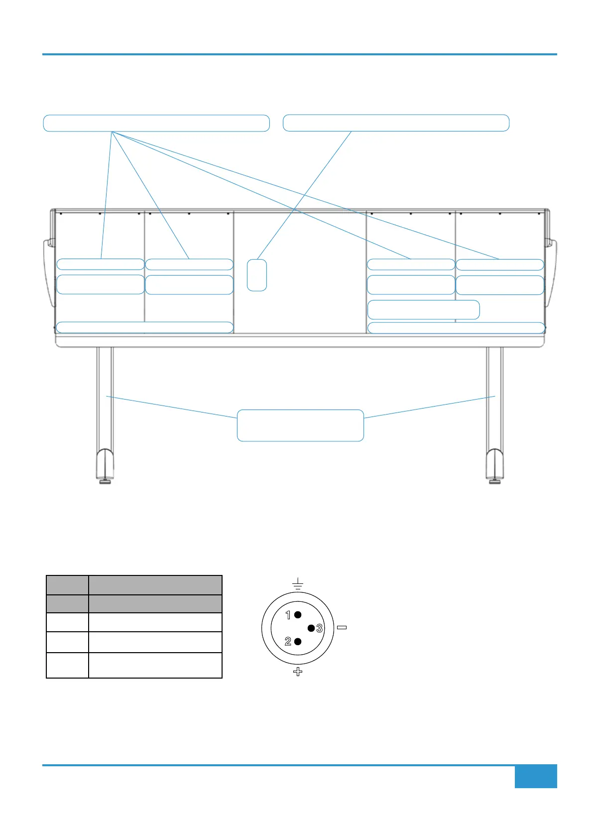
Origin Rear View - Power and Audio Connectors
Location of the main audio and power connections are shown in the diagram below looking towards the rear of the console.
Audio Connector Details
Microphone Inputs
XLR connectors to Channel Mic Pre-Amplifiers
Channels 32 - 25
Channels 24 - 17 Channels 16 - 9
Channels 8 - 1
DB-25 x 7
Channels 32 - 25
DB-25 x 7
Channels 24 - 17
DB-25 x 7
Channels 16 - 9
DB-25 x 7
Channels 8 - 1
Leg rears are hollow to
allow use for cable access
IEC Power Inlets and Main Power Switch
DB-25 x 13, DB-9 x 1
Master Section Audio & Utility
Cable Tray
Cable Tray
CONSOLE REAR
3-pin XLR Female
Pin Description
1 0V Chassis
2 Signal +ve (Hot)
3 Signal -ve (Cold)