ORIGIN Installation Guide
Making Connections
23
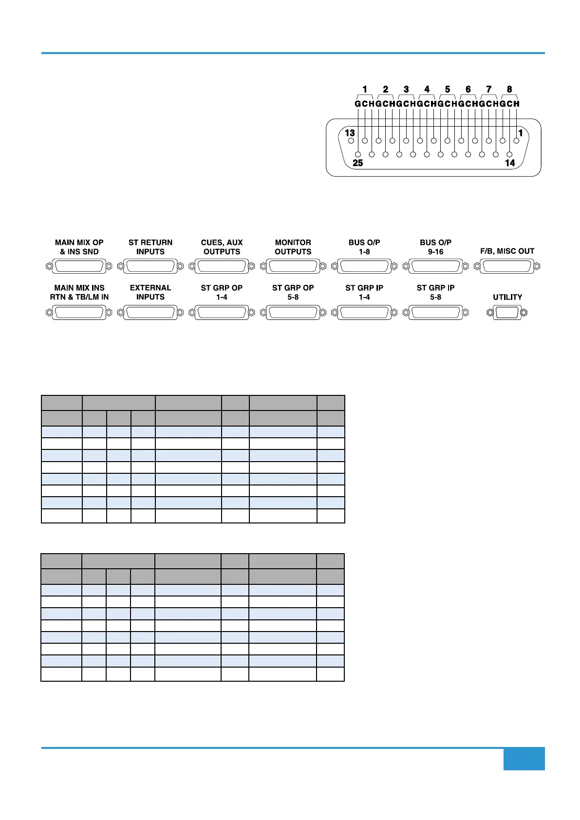
Master Section DB-25 Connectors
The Master Section audio connections are on the rear panel of the
console as a group of 13 female DB-25 connectors under the Channel
DB-25 Connectors for Channels 9-16.
Each connector uses the common AES59 format for analogue audio
DB-25 connectors, the pinout is shown on the right.
The physical layout of the Thirteen connectors is shown below as
viewed when looking at the rear of the console.
DB-25 Line Level Audio Connector Layout for the Master Section (all female connectors)
Master Section DB-25 Pinouts
**NOTE: Patch Reference on following tables only applies if using suggested standard patch layout on Page 26
Bus O/P (Bus Outputs)
25 Way F D-type Patch Patch
Cct# Hot Cold Scrn Bus Output 1-8 Ref** Bus Output 9-16 Ref**
1 24 12 25 Bus Output 1
A33
Bus Output 9
A41
2 10 23 11 Bus Output 2
A34
Bus Output 10
A42
3 21 9 22 Bus Output 3
A35
Bus Output 11
A43
4 7 20 8 Bus Output 4
A36
Bus Output 12
A44
5 18 6 19 Bus Output 5
A37
Bus Output 13
A45
6 4 17 5 Bus Output 6
A38
Bus Output 14
A46
7 15 3 16 Bus Output 7
A39
Bus Output 15
A47
8 1 14 2 Bus Output 8
A40
Bus Output 16
A48
ST GRP IP (Stereo Group Inputs)
25 Way F D-type Patch Patch
Cct# Hot Cold Scrn St Grp IP 1-4 Ref** St Grp IP 5-8 Ref**
1 24 12 25 St Grp IP 1L
B33
St Grp IP 5L
B41
2 10 23 11 St Grp IP 1R
B34
St Grp IP 5R
B42
3 21 9 22 St Grp IP 2L
B35
St Grp IP 6L
B43
4 7 20 8 St Grp IP 2R
B36
St Grp IP 6R
B44
5 18 6 19 St Grp IP 3L
B37
St Grp IP 7L
B45
6 4 17 5 St Grp IP 3R
B38
St Grp IP 7R
B46
7 15 3 16 St Grp IP 4L
B39
St Grp IP 8L
B47
8 1 14 2 St Grp IP 4R
B40
St Grp IP 8R
B48