ORIGIN Installation Guide
Making Connections
25
Master Section DB-25 Pinouts Cont'd
**NOTE: Patch Reference on following tables only applies if using suggested standard patch layout on Page 26
Mix Bus INS RTN (Insert Return) and TB/LM (Talkback/Listen Mic) Line Inputs
25 Way F D-type Main Ins Rtn Patch
Cct# Hot Cold Scrn Talkback/Listen Ref**
1 24 12 25 Main Ins Rtn L
L33
2 10 23 11 Main Ins Rtn R
L34
3 21 9 22 N/C
L35
4 7 20 8 N/C
L36
5 18 6 19 TB Line In
L37
6 4 17 5 Listen Line In
L38
7 15 3 16 N/C
L39
8 1 14 2 N/C
L40
9
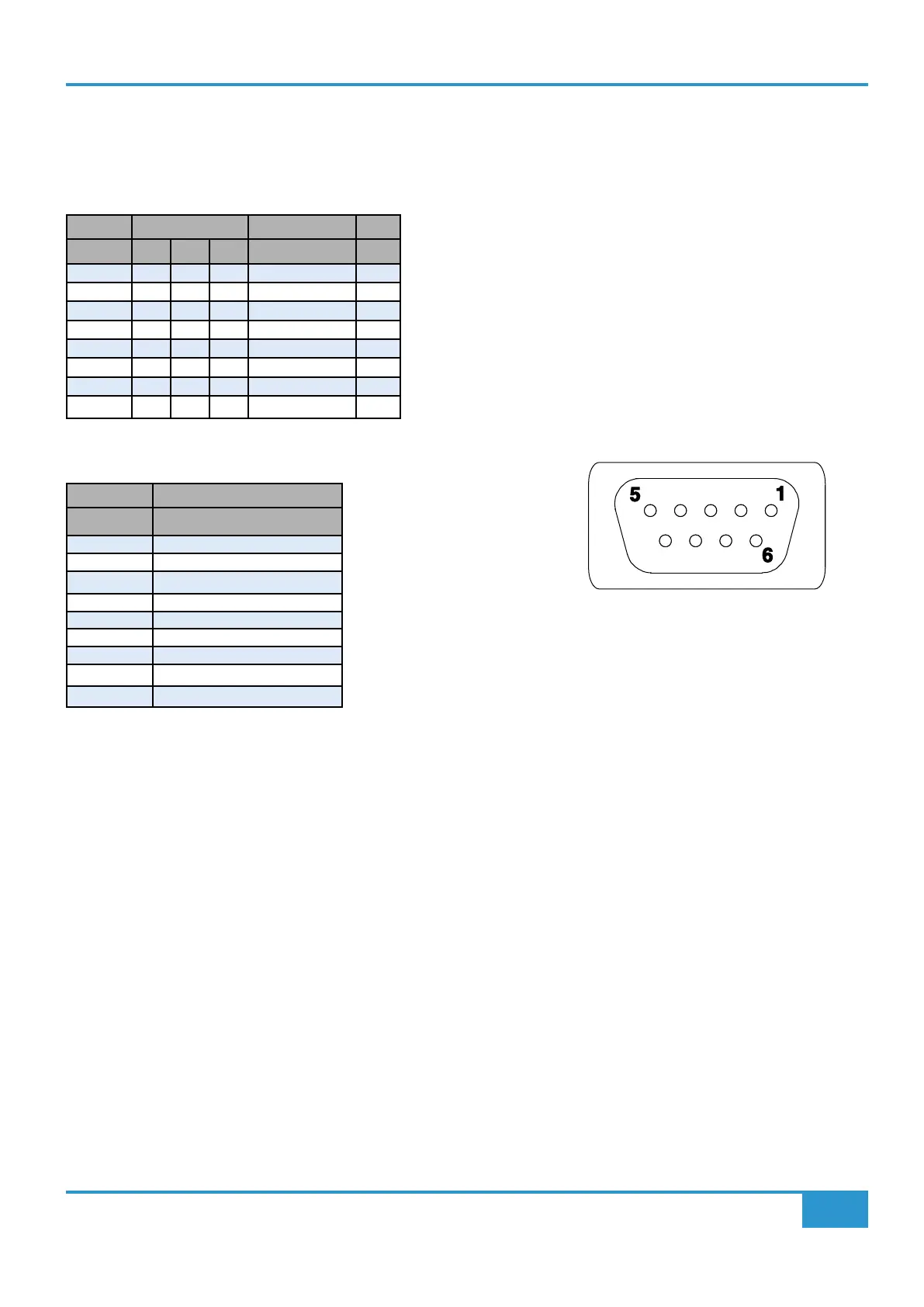
UTILITY
9-Way F D-type
Pin
Red Light Relay
1 Normally Open Contact R1
2 Common
3 Normally Closed Contact R1
4 Normally Open Contact R2
5 Common
6 Normally Closed Contact R2
7 N/C
8 N/C
9 N/C
R1 and R2 are separate relays, both operated by the Red Light Switch