SiX User Guide
Appendix A
27
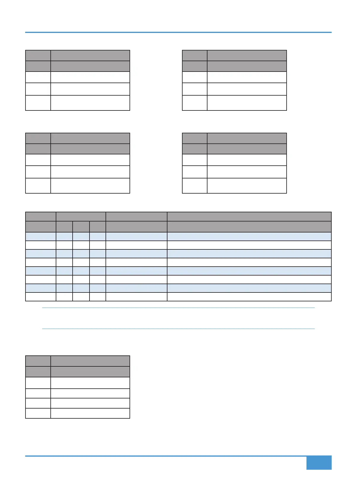
Main Bus Outputs
3-pin XLR Male
Pin Description
1 0V Chassis
2 Signal +ve (Hot)
3 Signal -ve (Cold)
Main Monitor Outputs
1/4" TRS Jack Socket
Pin Description
Tip Signal +ve (Hot)
Ring Signal -ve (Cold)
Sleeve 0V Chassis
Bus B Outputs
1/4" TRS Jack Socket
Pin Description
Tip Signal +ve (Hot)
Ring Signal -ve (Cold)
Sleeve 0V Chassis
Alternate Monitor Outputs
1/4" TRS Jack Socket
Pin Description
Tip Signal +ve (Hot)
Ring Signal -ve (Cold)
Sleeve 0V Chassis
Insert Sends/Returns, Alternate Inputs and Auxilliary Outputs
25 Way D-type Input D-Type Output D-Type
Circuit # Hot Cold Scrn Circuit Description Circuit Description
1 24 12 25 Main L Insert Return Main L Insert Send
2 10 23 11 Main R Insert Return Main R Insert Send
3 21 9 22 Channel 1 Insert Return Channel 1 Insert Send
4 7 20 8 Channel 2 Insert Return Channel 2 Insert Send
5 18 6 19 Channel 1 Alt Input Main L Output - (Passive Split, Not Buffered Output)
6 4 17 5 Channel 2 Alt Input Main R Output - (Passive Split, Not Buffered Output)
7 15 3 16 MON L Output** - (Passive Split, Not Buffered Output)
8 1 14 2 MON R Output** - (Passive Split, Not Buffered Output)
** NOTE: Monitor outputs on D-Sub connecter are not muted by ‘ALT’ speaker switch. The ALT
switch only affects the main monitor output on rear TRS Jack connectors.
DC Power Inlet
5-pin XLR Male
Pin Description
1,2,3 Not Connected
4 0V Common
5 +15 V, 3.3 A
Shell Chassis