17
4.Installation
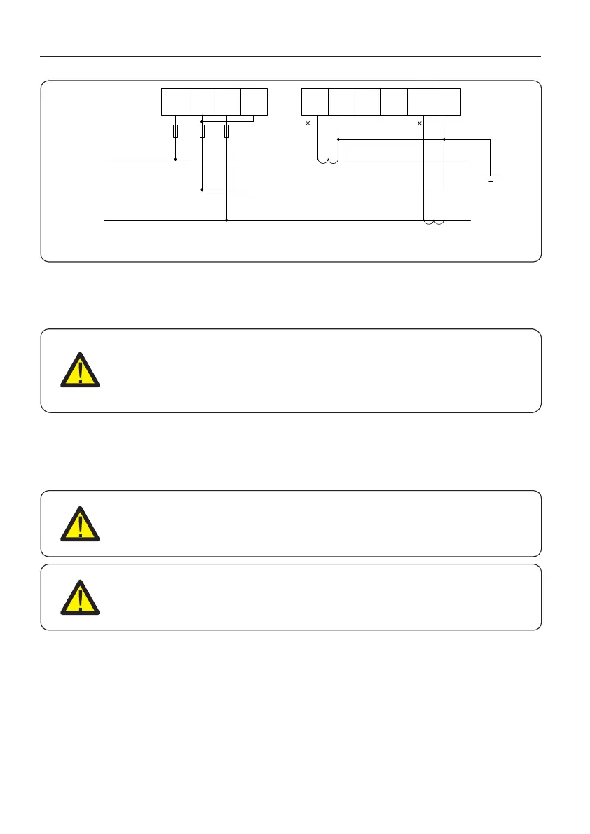
Figure 4.16 Three phase four lines connect via CT
L1
L2 L3
Ia* Ia Ib* Ib Ic* Ic
N
L1
L2
L3
To detect the backflow power, the CTs need to be installed at the PCC
(Point of Common Coupling), instead of the load branch circuit.
NOTE:
For three phase system, CT must be installed on U,V and W with correct
sequence, otherwise EPM can not detect the correct data.
“The CT cable outer diameter is 6.5mm-7.5mm, cross-sectional area 1.5mm²”.
a. Switch off the main switch, disconnect the line cables.
b. Insert the cables through the CT, make sure the P1 on CT is towards grid and P2 is
towards the inverter.
c. Reconnect the line cables.
4.3.4 Connect and fix the CT
NOTE:
If the CT is installed in the wrong direction, the EPM can't work normally.
NOTE:
The CT must be grounded on the secondary side.

 Loading...