12
4.Installation
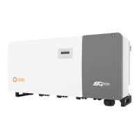
Figure 4.6 EPM3-5G-PRO middle and high voltage side system connection diagram
PV
PV
Solis Inverter
EPM
Data Stick
SolisCloud
PV Plant Digital
Management System
Grid
Loads
Internet
RS485 Communication Cable
Communication DC AC
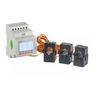
Smart Meter
(optional)
Step-up Transformer SwitchGear
a. Measure the distance from EPM to power distribution box. And find proper cable for
grid input. Use 5 core cable for Solis EPM3-5G-PRO.
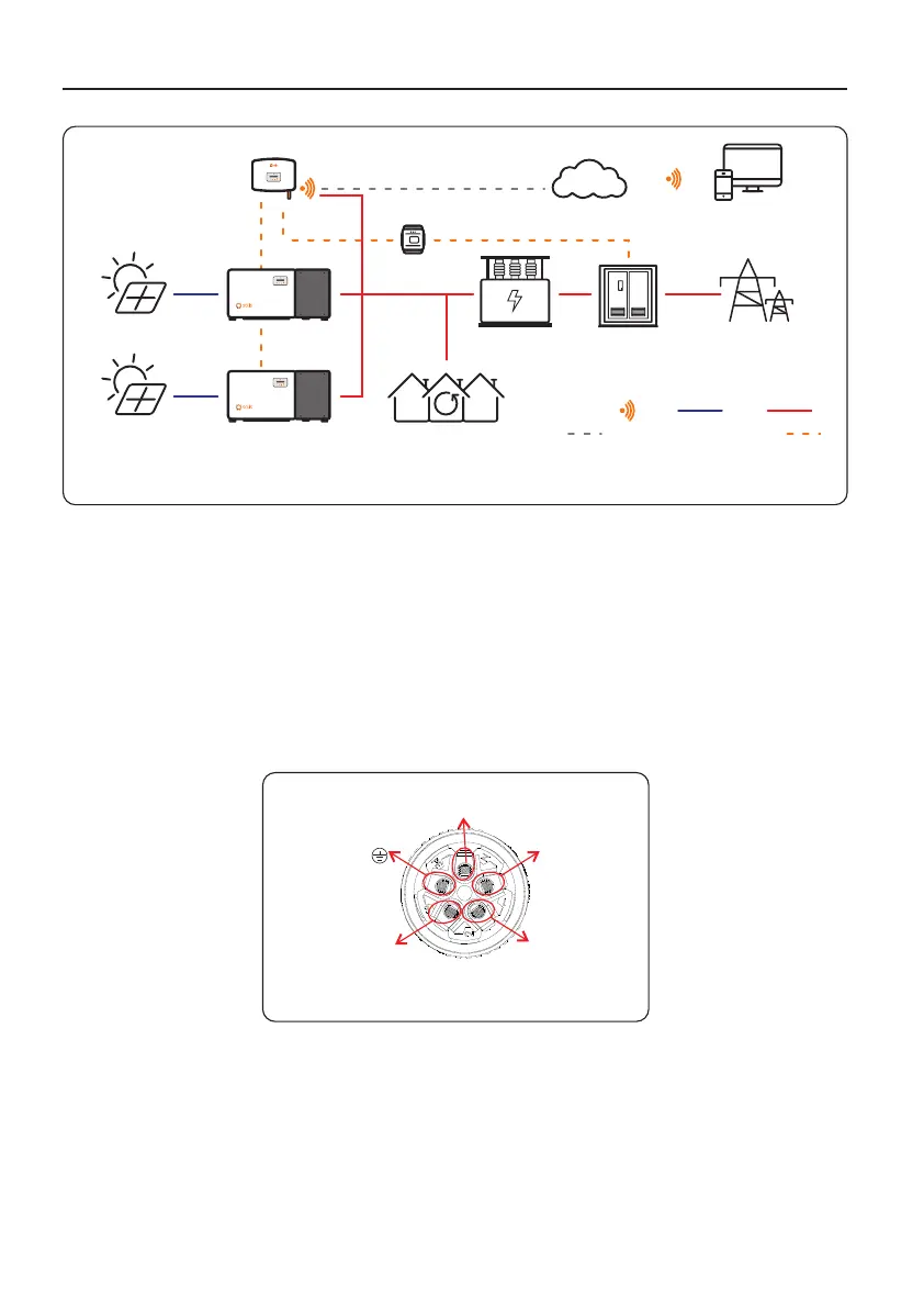
b. Connect L1, L2, L3, N and PE to pins 1, 2,3, N and PE. (see figure 4.8).
Figure 4.7 Three phase connection
Connect
Pin-3 to L3
Connect
Pin-N to N
Connect to PE
Connect
Pin-2 to L2
Connect
Pin-1 to L1
4.3.1 Make the Grid input cable
 Loading...