19
5.Comissioning and Decommissioning
1. Switch off all the AC breakers and DC breakers in the system.
2. Complete AC and DC wirings for inverters by following inverter manuals.
3. Connect AC cables to the Grid terminal on the EPM.
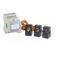
4. Install the CTs to the grid connection side with correct direction as mentioned in EPM
manual.
5. Connect RS485 communication cables between inverters and EPM Comm-INV port.
6. Switch on the DC breakers for Inverters and set the inverters to "OFF" in LCD and
Set "External EPM Set"- "5G EPM" -"Failsafe: ON". Then assign slave addresses
accordingly in inverters.
7. Switch on all the AC breakers for inverters and EPM
8. Set EPM settings including“Inverter Qty Set”, "Backflow Power", "Set CT Ratio" and
"Set Capacity" based on the actual system configuration.
9. Turn on some loads and check the power flow data on EPM. Negative power indicates
taking power from grid and CT direction is correct. Positive power indicates export power
to grid and the CT direction is reversed (Change the CT direction accordingly).
10. If the CT direction is confirmed correct and EPM is not reporting any alarms, set all
inverters to ON in inverter LCD.
11. Commissioning Completed.
5.1 Commissioning
5.2 Decommissioning
To avoid backflow power to the Grid, please stop the inverter before stopping the EPM.
1. Turn off the inverter output AC breaker.
2. Turn off inverter input DC breaker or pull out PV cable to stop inverter.
3. Turn off the grid input breaker of EPM.
4. Disconnect all cable of EPM, disassemble EPM after 5mins.

 Loading...