18
4.Installation
Please follow the previous system diagrams to connect multiple inverters.
EPM can control max 60 inverters (different models are allowed).
The system can ONLY has one grid connection point.
Inverters that are connected to EPM can be monitored by Solis Monitoring devices.
(Wi-Fi/Cellular/LAN stick)
NOTE:
When inverter is connected to EP M, no other monitoring device is allowed to
be connected to the inverter.
NOTE:
Solis recommends customers to purchase suitable current transformers from
local suppliers according to the max possible current in different projects.
As long as the secondary current is 5A, no matter what the primary current is,
it will not affect the warranty of the EPM devices and inverters.
Solis can also provide above current transformers as an optional accessory.
Customers can contact Solis sales rep to place the order based on their project
requirements.
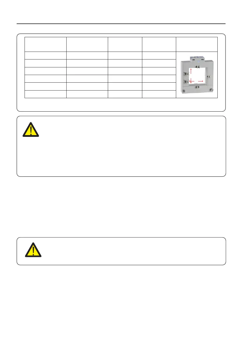
Table 4.2 CT Ratio
Specification
CT-30×20-100A
CT-60×40-300A
CT-80×40-600A
CT-80×40-1000A
CT-160×80-2000A
CT-160×80-3000A
AKH-0.66K
a
e
Dimensions(mm)
W x H x D
90 x 114 x 40
114 x 140 x 36
122 x 162 x 40
122 x 162 x 40
184 x 254 x 52
184 x 254 x 52
Hole size(mm)
a x e
22 x 32
42 x 62
42 x 82
42 x 82
82 x 162
82 x 162
CT Ratio
100:5A
300:5A
600:5A
1000:5A
2000:5A
3000:5A
4.3.5 Multi-inverter connection
4.3.6 Monitoring

 Loading...