14
4.Installation
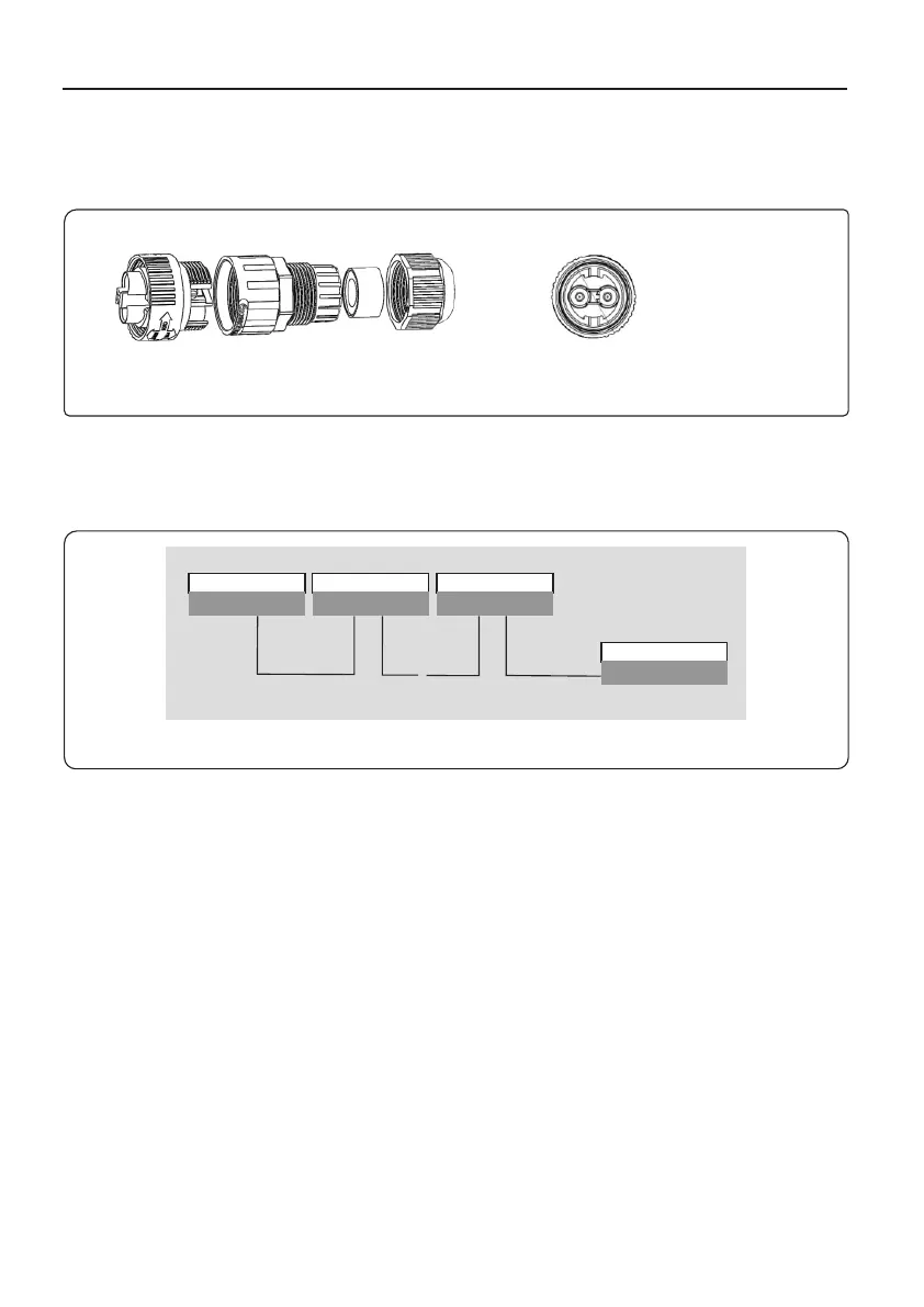
a. Refer to figure 4.16, the RS485 terminals for inverter and EPM are already assembled.
Tips:RS485 cable: preferred 0.5mm², max 1.0mm².
.
Figure 4.11 RS485 terminal
b. Refer to figure 4.16, connect communication cable between inverter with EPM, and
then measure the distance from EPM to inverter. Use proper cable for RS485
connection. (0.5mm²)
c. Follow step1 to assemble 2 connectors to each end of cable.
≈
Inverter 1 Inverter 2 Inverter n
Rs485 I N | O UT
Rs485 I N | O UT
Rs485 I N | O UT
Rs485terminal
EPM BOX
Figure 4.12 RS485 cable connection
+ to connect RS485 A
- to connect RS485 B
φ25.5
4.3.2 Make RS485 cable(COMM-INV port)
 Loading...