31
7. Troubleshooting
The EPM is designed in accordance with the most important international safety and
EMC requirements. Before delivering to the customer, the EPM has been subjected to
several tests to ensure its optimal operation and reliability.
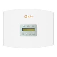
In case of failure, the LCD screen will display alarm message.
The EPM can show its own alarms or alarms from inverter. There are 3 alarm can be
showed on LCD:
1. Backflow
There is backflow current to the grid, customer needs to stop inverter and check the
connections for the RS485 cable between EPM and inverter.
2. INV. fault
There is a fault alarm in inverter, need to check inverter status.
3. Fail safe
RS485 AllFail: EPM has lost communication with ALL inverters
CT-Failsafe: Current Sensor failed
RS485Fail: EPM has lost communication with one or some of the inverters

 Loading...