.12..13.
5. Installation5. Installation
+
-
DC 1
DC 2
DC SWITCH
COM
GRID
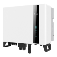
Locking screws
Figure 5.5 Install the inverter
Figure 5.6 Fixed the inverter
WARNING:
The inverter must be mounted vertically.
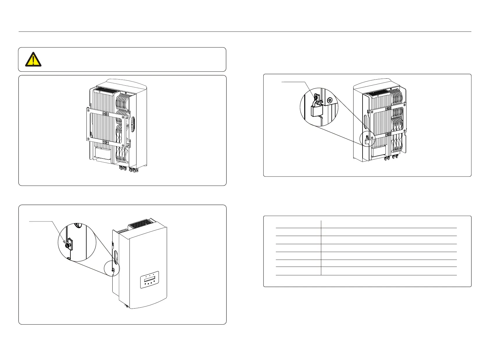
5. Anti-theft lock mount(optional)
Anti-theft lock( User-supplied) function is that inverter is fixed in bracket in case theft.
The lock is selected by 5mm(the keyhole diameter), and the lock of stainless steel is
preferred.
Anti-theft lock
Figure 5.7 Install security lock
5.3 Electrical Connections
Inverter designs quick-connect terminal, so top cover needn't open during electrical
connection. The sign meaning located the bottom of inverter, as shown below in table 5.1.
All electrical connections are suit for the local or national standard.
Positive DC input terminal
Negative DC input terminal
Connecting terminal of the Grid
Switch of DC input terminals
RJ45 and terminal block for RS485 communication port
DC input terminal
DC input terminal
Table 5.1 Electrical connection symbols
The electrical connection of the inverter must follow the steps listed below:
1. Switch the Grid Supply Main Switch (AC) OFF.
2. Switch the DC Isolator OFF.
3. Assemble PV input connector to the Inverter.
4. Lift the inverter and hang it on the backet, and fixing both sides of inverter with
locking screws (accessories).

 Loading...