User Manual
Refer to figure 3.3, figure 3.7 and figure 3.8 Inverter shall be mounted upright, with electrical
connections downward. The steps to mount the inverter are listed below.
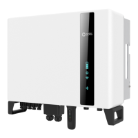
1. Refer to Figure 3.7, drill holes for mounting screws based on the hole diameter of
bracket using a precision drill keeping the drill perpendicular to the wall.
Max depth is 3.5 inch.
2. M ake sure the bracket is horizontal. And the mounting holes (in Figure 3.7) are marked
correctly. Drill the holes into wall at your marks.
3. Use the suitable mounting screws to attach the bracket on the wall.
3.3.1 Wall mounting
Figure 3.8 Install the inverter
4. Lift the inverter and hang it on the bracket, and then slide down to make sure they
match perfectly.
Figure 3.7 Inverter wall mounting
Bracket
Suitable mounting screws
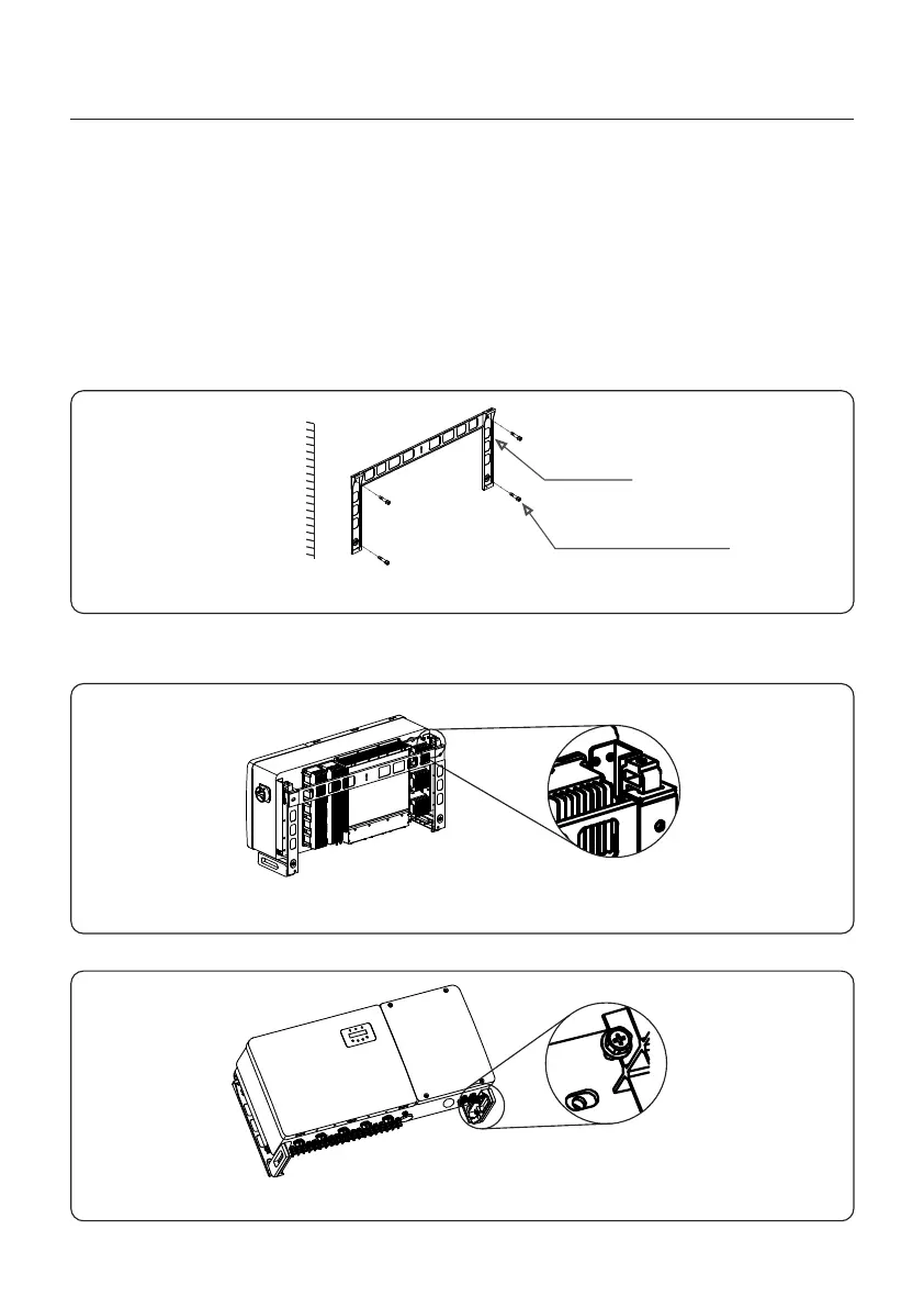
Figure 3.9 Secure the inverter
5. Use supplied 2 M6x12 hex bolts to secure the inverter to the bracket.
Torque:22.1-25.8 ft.lbs
Torque:1.5-2.2 ft.lbs
3. Installation
16

 Loading...