4. Installation4. Installation
4.3.2 AC output connections
It is recommended to use 6-16mm2 outdoor cables with a crimp terminal range of 6-10mm2.
Installation steps are shown as below:
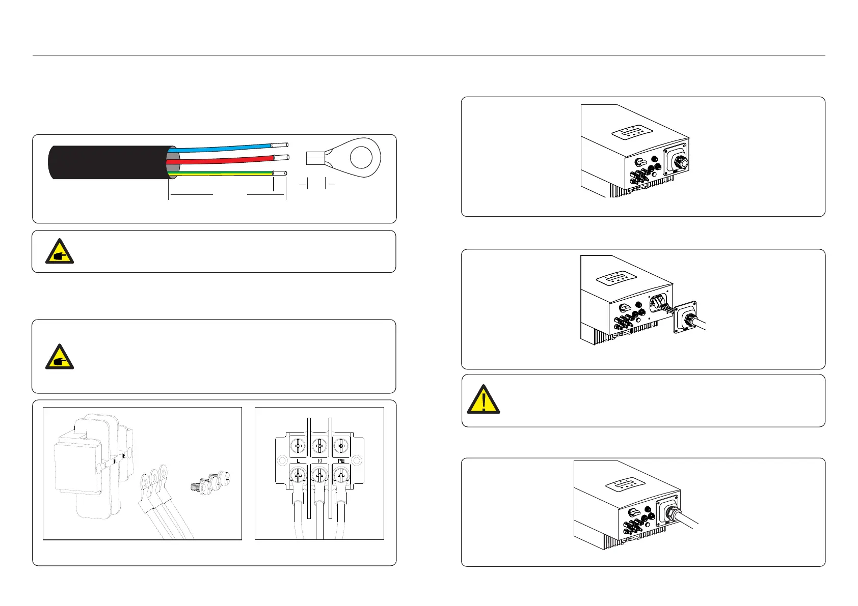
1. Strip the end of the AC cable insulation sleeve about 55mm then strip a short bit (S2)on the
end of each wire.
.17..16.
PE
N
L
S1
55MM
S2
Figure 4.15 Stripped AC Wires
NOTE:
S2 (the length to strip the wire is about 8mm) which is 2-3mm longer than S1.
2. Insert the stripped cable into the crimping area of the OT terminal then use crimping tool to
crimp the cable terminal .
The terminal part must be insulated with heat shrink tubing or insulating tape.
NOTE:
If aluminum cables are used, please use copper and aluminum terminals
to avoid direct contact between the copper bar and the aluminum cables.
(the copper and aluminum adapters are configured according to the selected
cable)
Figure 4.16 Copper-aluminum transition terminal
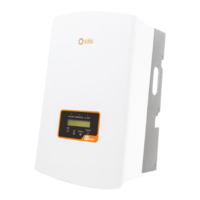
3. Dissemble the 4 screws on the AC terminal cover and take out the cover.
Figure 4.17 Disassemble AC terminal cover
4. Insert the cable through cap nut, tubing and AC terminal, Insert the 3 cables into AC terminal
and use the slotted screwdriver to tighten the screws with torque of 2-3Nm.
Figure 4.18 Connect cable to AC terminal
WARNING:
When assembling the AC terminal, be careful not to cut the insulation layer of
the wire, or it might lead to poor contact.
5. Push the AC terminal along the rail to the inside of the inverter then tighten the screws.
Lock the 4 screws of the AC terminal then tighten the cap nut.
Figure 4.19 Tighten the AC terminal