6. Operation6. Operation
6.5.10 Restore Settings
Please follow below settings to enable the DRM. DRM default setting is “OFF” , if DRM set “ON”,
but the logic interface un-connected to the switch or the switch is open, the inverter HMI will
display “Limit by DRM” and the inverter output power will be limited to zero.
1. Select Initial Settings
2. Select DRM and set it “ON”
Restore setting could set all item in 6.5.8 special setting to default.
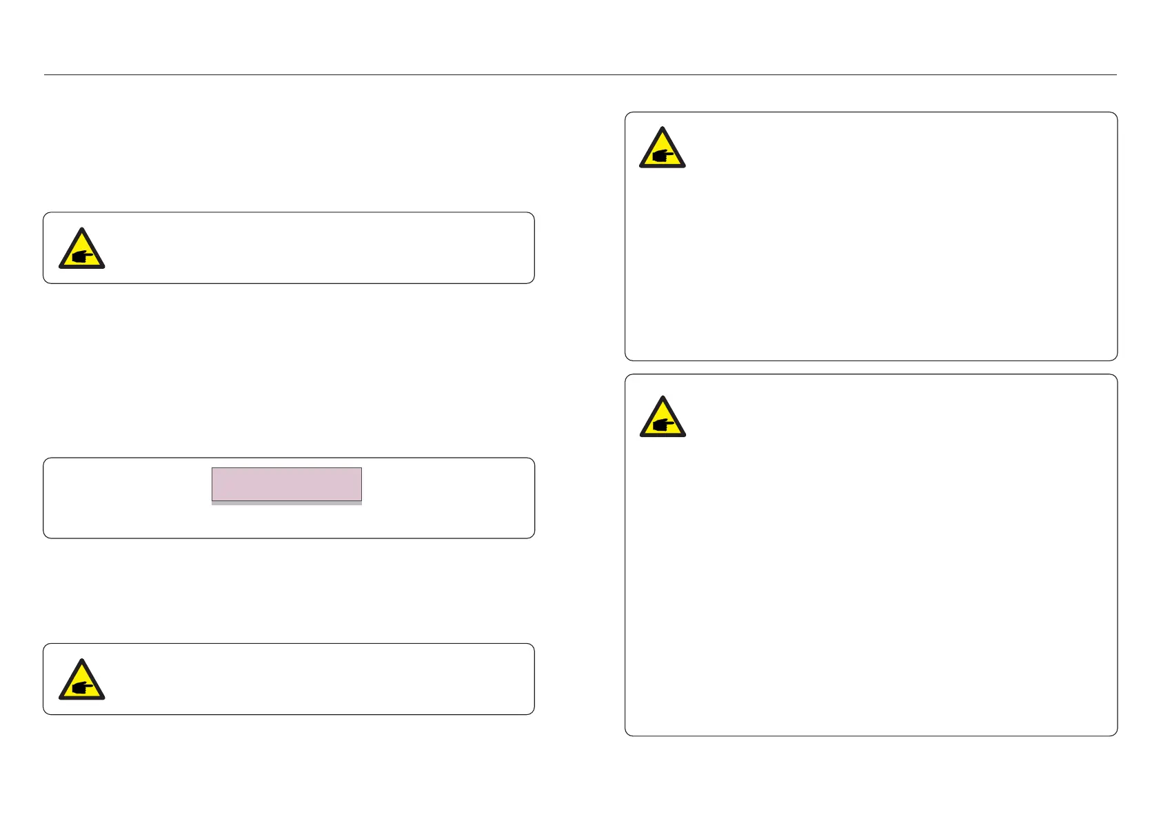
Thescreenshowsasbelow:
Figure 6.22 Restore Settings
Are you sure?
YES=<ENT> NO=<ESC>
PresstheEnterkeytosavethesettingaftersettinggridoff.
PresstheESCkeytoreturnthepreviousmean.
6.5.11 HMI Update
This function is used for updating the LCD program.
6.5.12 Internal EPM Set
This section includes two functions related to the smart meter or smart sensor.
Please refer to section 4.3.7 or 4.3.8 for detailed connection diagrams.
Function 1: Internal Export Power Management Function
Inverters can work with a smart meter OR a smart sensor to dynamically limit
the export power of the system. Zero injection can be achieved.
Smart meter can be installed either on the grid side OR the load side.
Smart sensor can only be installed on the grid side.
Function 2: 24 Hour Consumption Monitoring Function
Only applicable if Solis monitoring system is used.
Inverters can work with a smart meter to monitor the load consumption data
for the whole day and the data will be displayed on the Solis monitoring system.
Smart meter can only be installed on the grid side.
Please refer to below instructions for different user scenarios.
Scenario 1. Only Function 1 is required
Using a Smart Meter:
Step 1: Refer to Section 4.3.7 to connect the smart meter on the grid side or
load side.
Step 2: Select the corresponding meter model in Section 6.5.12.4
Step 3: Select the Section 6.5.12.1 Mode Select as Option 2(Meter in Load)
or Option 3 (Meter in Grid) accordingly.
Step 4: Configure the Section 6.5.12.2 to set the allowed backflow power.
Step 5: Configure the Section 6.5.12.3 to enable the failsafe function
(If necessary).
Using a Smart Sensor:
Step 1: Refer to Section 4.3.8 to connect the smart sensor on the grid side.
Step 2: Select the Section 6.5.12.1 Mode Select as Option 5(Current Sensor).
Step 3: Configure the "CT Sampling Ratio" and "CT Link Test" if necessary.
Step 4: Configure the Section 6.5.12.2 to set the allowed backflow power.
Step 5: Configure the Section 6.5.12.3 to enable the failsafe function
(If necessary).
6.5.9 STD Mode settings
There are 5 setting under STD. Mode settings.
1. Working mode
2. Power Rate limit
3. Freq. Derate set
4. 10mins OV-G-V set.
5. Initial Settings
This function is applicable by maintenance personnel only, wrong operation
will prevent the inverter from reaching maximum power.
This function is applicable by maintenance personnel only, wrong operation
will prevent the inverter from reaching maximum power.
NOTE:
NOTE:
.37..36.
 Loading...