6. Operation6. Operation
If the users want execute the Internal Export power management
function or 24H Consumption load Monitoring function by Smart
Sensor.
Please refer to the below instruction for different demands:
Scenario1: Both Internal Export power management Consumption and
24H Consumption load Monitoring by Smart Sensor.
Step 1: Refer the Section4.3.8 to connect the smart sensor on the grid
side.
Step 2: Select the Section 6.5.12.1 Mode Select as Option 6(Current
Sensor).
Step 3: Configure the "CT Sampling Ratio" and "CT Link Test" if necessary.
Step 4: Select the Section 6.5.3 24H Switch as "Enable".
Step 5: Configure the Section 6.5.12.2 to set the allowed backflow power.
Step 6: Configure the Section 6.5.12.3 to enable the failsafe function
(If necessary).
Step 7: Configure the Solis monitoring system (Please refer to the manual
of monitoring device)
Scenario2: Only 24H Consumption load Monitoring function by Smart
Sensor.
Step 1: Refer to Section 4.3.8 to connect the smart sensor on the grid side.
Step 2: Select the Section 6.5.12.1 Mode Select as Option 5
(LoadMonitor_CT).
Step 3: Select the Section 6.5.3 24H Switch as "Enable".
Step 4: Configure the Solis monitoring system (Please refer to the manual
of monitoring device).
NOTE:
There are 3 states in the CT Link Test
"Error" means the CT is installed in the wrong direction, please change it.
"Can not judge" means the load power is too small and the result is not credible.
"Correct" means the CT is installed correctly.
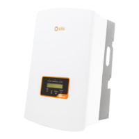
Inverter
CT Input L N
L N
Load
N
L
CT
Grid
CT
CT
√
×
×
NOTE:
For option 5 (Current sensor), there are several sub-settings available
when "Current sensor" is selected.
·CT Link Test
This setting is used to check the direction of the CT (Not complusory)
The result is only valid if the following conditions are met.
1. Load power is over 500W.
2. Inverter is set as "Grid OFF" in the LCD.
3. CT is connected to the inverter CT port and the CT is placed at the grid side.
·CT Sampling Ratio
This setting is used to define the CT sampling ratio if customer didn't use the
default CT supplied by Solis.
The default CT is 100A:33.33mA (Default ratio is 3000:1)
-> CT Sampling Ratio
YES=<ENT> NO=<ESC>
Ratio:3000:1
CT Link State
Correct
NOTE:
.42. .43.