23
Chapter 2 Hardware Setup
Clock
Generator
J2
J3
SPK RST KEYLOCK T/LED
HDD/LED IR PWR SUSPEND
++
--
+
-
1 15
1 15
I/O
Controller
FWH
Intel
ICH2
SOCKET 370
LPT1
COM1COM2
GAME/MIDI PORT
LINE
OUT
LINE
IN
MIC
Intel
82815EP
MCH
Li
Battery
RT1
DIMM2
DIMM1
DIMM3
PCI 1
PCI 2
PCI 3
PCI 4
PCI 5
JWOL1
CD_IN1
CD_IN2
CNR1
SCR1
IDE2
IDE1
FDC1
CPUFA1
ATX POWER
AUXFA1
1
11
1 3
1 3
JP5
JP6
CHAFA1
RT2
AC'97
Codec
1 3
1 3
1 3
JBAT1
JBAT2
JP16
USB1
1
16
1 3
1 3
1 3
PS/2
MOUSE
PS/2
K/B
upper
lower
USB1
USB0
upper
lower
1 4
1 4
1 3
JP1
AGP 4X
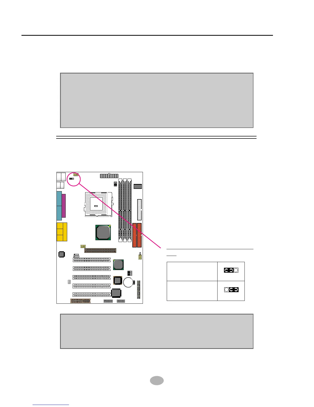
2-4 Jumper Setting For Devices On Board
• The following diagrams show the locations of jumper blocks on the
mainboard.
CAUTION
• Do not remove the jumper when power is on. Always make sure the
power is off before changing any jumpers. Otherwise, mainboard could
be damaged.
• In diagrams below, all jumper pins covered with black marks stand for
closed pins.
• All jumper pins covered with black marks are closed pins.
2-4.1 JP1 Keyboard/Mouse Power On
PS/2 Keyboard/Mouse Power
On:
NOTE: This function allows you to use PS/2 keyboard or PS/2 mouse
to power on your system. The function must be set in conjunction with
“Power on function” state in BIOS setup “Integrated peripherals”
section.
13
JP1
13
JP1
Disabled (default)
Enabled