27
Chapter 2 Hardware Setup
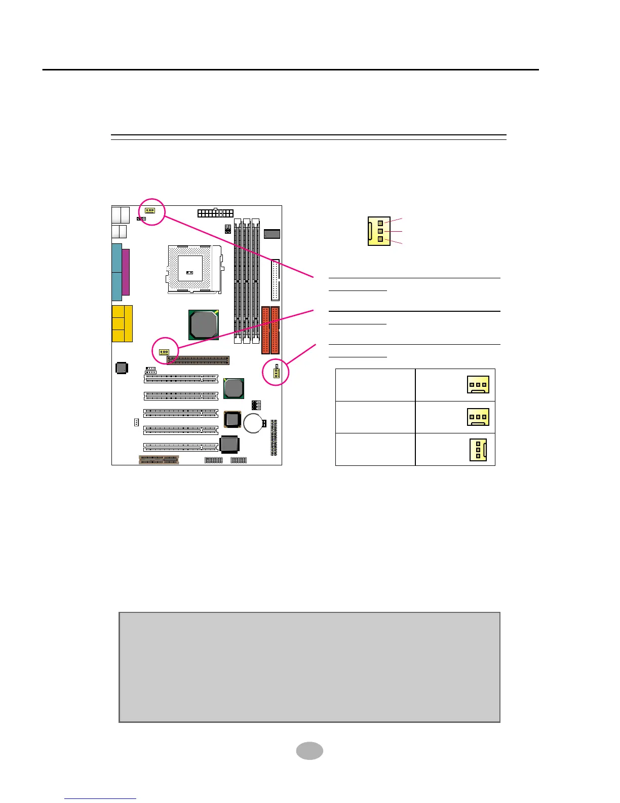
These fan connectors support CPU/System/chassis cooling fan with +12V.
When connecting wire to FAN connectors, users should pay attention
that the red wire is for the positive current and should be connected to
pin +12V, and the black wire is Ground and should be connected to pin
GND. If your mainboard has Hardware Monitor chipset on-board, you
must use a specially designed fan with speed sensor to take advantage
of this function.
For fans with speed sensors, each rotation of the fan blades will send out
2 electric pulses, by which System Hardware Monitor will work out the
fan rotation speed by counting the pulses.
GND
+12V
SENSOR
2-5.1 On Board FAN Connector (CPUFA1, AUXFA1, CHAFA1)
2-5 CONNECTORS CONFIGURATIONS
• This section list out all connectors configurations for users’ reference.
Clock
Generator
J2
J3
SPK RST KEYLOCK T/LED
HDD/LED IR PWR SUSPEND
++
--
+
-
1 15
1 15
I/O
Controller
FWH
Intel
ICH2
SOCKET 370
LPT1
COM1COM2
GAME/MIDI PORT
LINE
OUT
LINE
IN
MIC
Intel
82815EP
MCH
Li
Battery
RT1
DIMM2
DIMM1
DIMM3
PCI 1
PCI 2
PCI 3
PCI 4
PCI 5
JWOL1
CD_IN1
CD_IN2
CNR1
SCR1
IDE2
IDE1
FDC1
CPUFA1
ATX POWER
AUXFA1
1
11
1 3
1 3
JP5
JP6
CHAFA1
RT2
AC'97
Codec
1 3
1 3
1 3
JBAT1
JBAT2
JP16
USB1
1
16
1 3
1 3
1 3
PS/2
MOUSE
PS/2
K/B
upper
lower
USB1
USB0
upper
lower
1 4
1 4
1 3
JP1
AGP 4X
On Board FAN Connector
(CPUFA1):
On Board FAN Connector
(AUXFA1):
On Board FAN Connector
(CHAFA1):
NOTE:
1. Always consult vendor for proper CPU cooling fan.
2. CPU FAN supports the FAN control. You can install PC Alert utility.
This will automatically control the CPU FAN speed according to the
actual CPU temperature.
3. We use 3 “Yellow” fan connectors to mark that they support fan speed
sensor function.