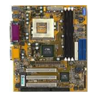
26
65KIV/KIV2
VIA
VT82C694X
VIA
VT82C
686A
LPT1
COM2 COM1
GAME/MIDI PORT
LINE
OUT
LINE
IN
MIC
AC'97
Codec
FLASH BIOS
ISA
FDD1
1
IDE2
IDE1
1
1
Li
Battery
DIMM1
DIMM2
DIMM3
PCI 1
PCI 2
PCI 3
AGP 4X
SPK RST PWR/LED T/LED
HDD/LED IR PWR SMI
CON1
++
--
+
-
S
W
1
O
N
D
I
P
1
2
3
4
5
6
7
8
ATX POWER
FAN1
FAN3
F
A
N
2
USB2
16
1
JWOL1
3
1
Clock
Generator
1 3
JBAT1
1 3
JP5
1 3
JP6
1 3
JP1
SOCKET 370
RT1
1 4
1 4
C
D
_
I
N
1
C
D
_
I
N
2
USB1
USB0
PS/2
MOUSE
PS/2
K/B
upper
lower
upper
lower
RT2
1
30
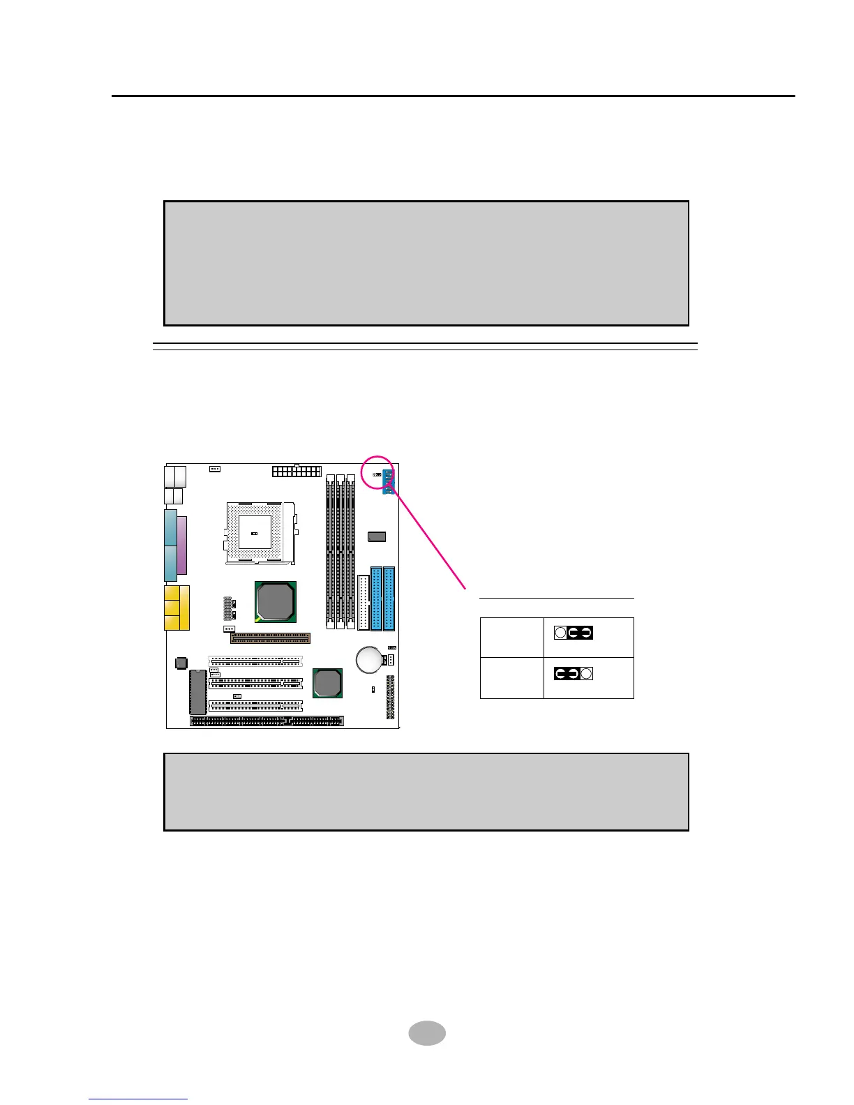
2-6.1 JP1 Power Lost Resume
Power Lost Resume:
NOTE: This jumper allows user to use the switch of ATX power supply to
control ON/OFF switch directly instead of using the power switch on the
mainboard.
Normal
(default)
13
13
JP1
JP1
Enabled
2-6 JUMPER SETTING FOR DEVICES ON BOARD
• The following diagrams show the locations of jumper blocks on the
mainboard.
CAUTION
• Do not remove the jumper when power is on. Always make sure the
power is off before changing any jumpers. Otherwise, mainboard could
be damaged.
• In diagrams below, all jumper pins covered with black marks stand for
closed pins.