29
Hardware Setup
VIA
VT82C694X
VIA
VT82C
686A
LPT1
COM2 COM1
GAME/MIDI PORT
LINE
OUT
LINE
IN
MIC
AC'97
Codec
FLASH BIOS
ISA
FDD1
1
IDE2
IDE1
1
1
Li
Battery
DIMM1
DIMM2
DIMM3
PCI 1
PCI 2
PCI 3
AGP 4X
SPK RST PWR/LED T/LED
HDD/LED IR PWR SMI
CON1
++
--
+
-
S
W
1
O
N
D
I
P
1
2
3
4
5
6
7
8
ATX POWER
FAN1
FAN3
F
A
N
2
USB2
16
1
JWOL1
3
1
Clock
Generator
1 3
JBAT1
1 3
JP5
1 3
JP6
1 3
JP1
SOCKET 370
RT1
1 4
1 4
C
D
_
I
N
1
C
D
_
I
N
2
USB1
USB0
PS/2
MOUSE
PS/2
K/B
upper
lower
upper
lower
RT2
1
30
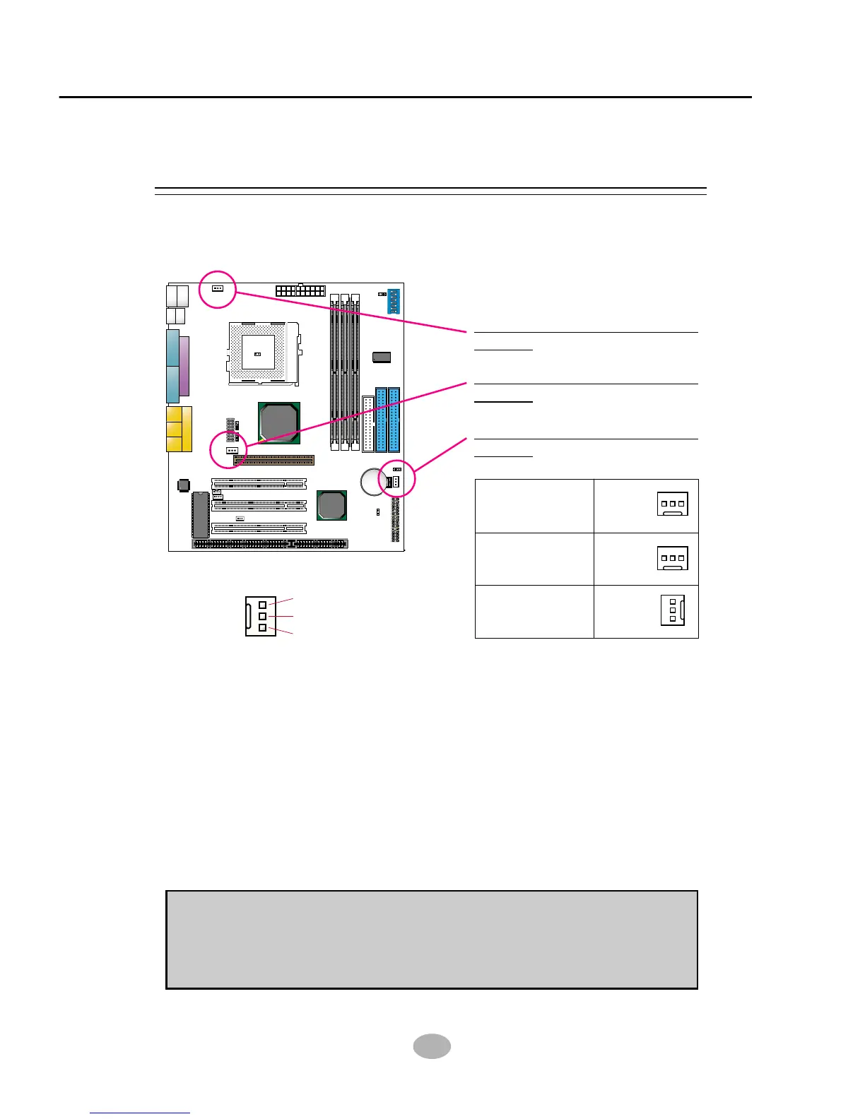
These fan connectors support CPU/System chassis cooling fan with +12V.
When connecting wire to FAN connectors, users should pay attention
that the red wire is for the positive current and should be connected to
pin +12V, and the black wire is Ground and should be connected to pin
GND. If your mainboard has Hardware Monitor chipset on-board, you
must use a specially designed fan with speed sensor to take advantage
of this function.
For fans with speed sensors, each rotation of the fan blades will send out
2 electric pulses, by which System Hardware Monitor will work out the
fan rotation speed by counting the pulses.
GND
+12V
SENSOR
2-7.1 On Board FAN Connector (FAN1, FAN2, FAN3)
2-7 CONNECTORS CONFIGURATIONS
• This section list out all connectors configurations for users’ reference.
On Board FAN Connector
(FAN1):
On Board FAN Connector
(FAN2):
NOTE 1: Always consult vendor for proper CPU cooling fan.
NOTE 2: CPU FAN supports the FAN control. You can install PC Alert
utility. This will automatically control the CPU FAN speed according to
the actual CPU temperature.