7 3/27/2015
6 Typical System Setups
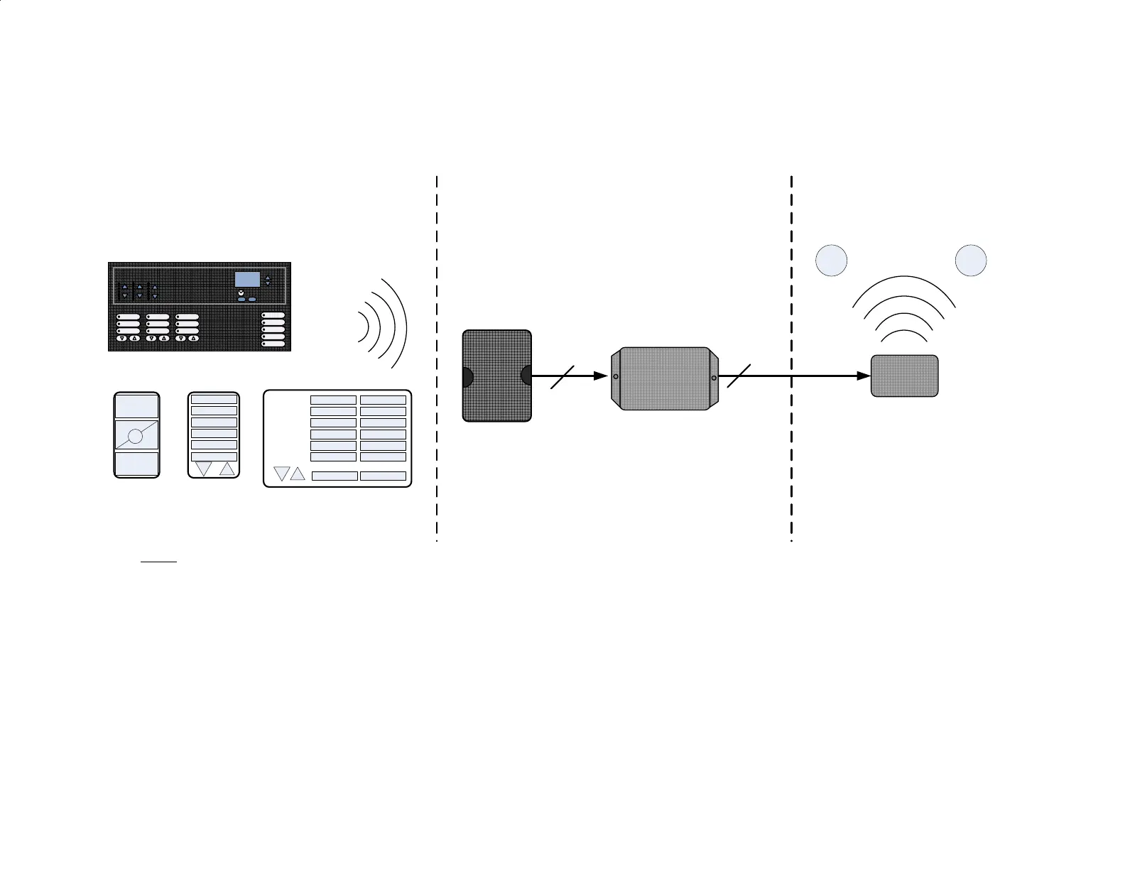
Somfy Connect – Radio RA2 to RTS
Typical Hardware Setup
Lutron
Main
Repeater
Somfy
Connect
Notes:
- Main Repeater requires a 115 VAC outlet.
- Power for Somfy Connect:
Option 1> Plug-in DC power to Somfy Connect. Power is carried over CAT5 to URTSI
Option 2> Connect power to URTSI. Power is carried over CAT 5 to Somfy Connect.
- The Main Repeater and Somfy Connect must be mounted within 50' of each other.
- Low Voltage connection from:
1 > Main Repeater to Somfy Connect: standard straight-thru RS232 cable
2 > Somfy Connect to URTSI: Cat 5
- Somfy Connect includes configuration software used to map RA2 button presses to URTSI functions (e.g. UP/STOP/DOWN)
- M1 & M2 are RTS motors, they require 115 VAC via a standard outlet or can be hard-wired.
1
2
Grafik Eye QS
Lutron RF
PICO
Keypad
with R/L
URTSI
M1 M2
Electrical Closet
RoomRoom
Table-Top