Operation and Maintenance Documentation GUARD v202301
6. CONTROL PANEL
A set of automatic control may be used (powered 230V) that consists of the following:
COMFORT NEW panel – including room thermostat and switch for regulation of 3 speeds of the fan.
One COMFORT panel may regulate up to 2 pcs of GUARD
2-way water valve with actuator; valve should be installed on a return stub of the heater
INTELLIGENT electronic control panel with an automatic speed controller, weekly program, and BMS communication.
One INTELLIGENT panel may regulate up to 2 pcs of GUARD
Splitter MULTI 6 - control up to 6 pcs of GUARD
The system is ready to start once the connections between the thermostat and the valve actuator are done, 230V power is
supplied to the thermostat and the fan’s motor is powered by the revs controlle.
COMFORT NEW panel description
OFF-I-II-III - switch and fan speed regulation
HEAT - the thermostat gives an operation signal to the actuator and fan, the fan turns off when the set
temperature is reached, the valve closes the water supply
FAN - device fan operation according to the thermostat, valves or electric heaters do not work
COOL - the thermostat gives an operation signal to the actuator and fan, the device starts to work
when the set temperature is reached
It is possible to use an additional change of the SR1 to SR1 CONST jumper position, in this case the fan can operate regardless
of the thermostat. Thermostatic operation is only for valves. In this case:
HEAT - fan operation regardless of the thermostat, valves work up to the set temperature
FAN - device fan operation, regardless of the thermostat, valves do not work
COOL - fan operation regardless of the thermostat, valves work from the set temperature
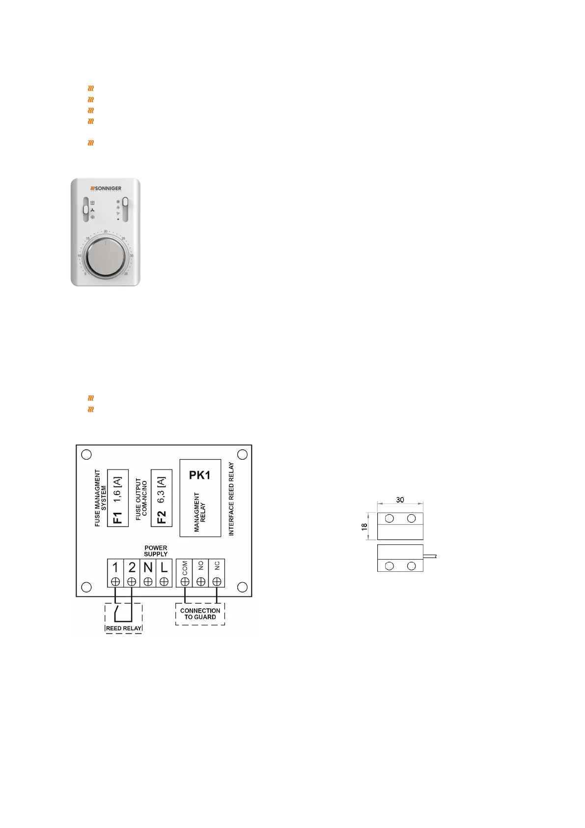
7. GUARD DOOR SWITCH
The GUARD (DC) door switch is an additional element for switching the curtain on/off, depending on the opening of the door.
It is designed for indoor installation. It includes:
Relay cabinet - reed relay switchboard
Reed relay - Reinforcement for door-fitting, hermetic magnetic switch, consisting of a movable and fixed element
Scheme of the relay cabinet – reed relay interface
When installing the GUARD door switch, remove the factory-made jumper:
NC-1 for curtain GUARD W (curtain with a water heater) / GUARD C (curtain without a water heater)
NC-COM for curtain GUARD E (curtain with an electric heater)
8. DIAGRAMS OF ELECTRICAL CONNECTIONS
The electrical network to which the curtain will be connected should protect against overheating and short-circuiting. It is
necessary to protect the air curtain by grounding. Electrical installation and connection to the air curtain must be following
applicable building codes and regulations, electrical connection should be carried out by a qualified person familiar with the
above instruction. The fan motor has standard internal thermal protection to protect the motor from overheating. The set does
not include: a power cord, or main switch
*diameter and length of the cable should be following local regulations (some deviations are acceptable)