14 (E)
Chapter 1 Overview
6 Input option slots (three slots)
The monitor may be fitted with optional input adaptors
up to three.
The BKM-129X is installed to the monitor at the
factory.
Notes
• The BKM-142HD uses two input option slots.
• Each adaptor can also be installed into SLOT 1.
Install any adaptor to SLOT 1.
Location and Function of Parts
For connecting the BKM-10R Monitor
Control Unit
Connect the monitor and control unit using a cable
with D-sub 9-pin plugs such as an RCC-5G (not
supplied) as follows:
SERIAL
REMOTE
IN
CTRL UNIT
BVM-D9H1U/D9H1E/D9H1A:
Set to CTRL UNIT.
Cable with D-sub
9-pin plugs
(not supplied)
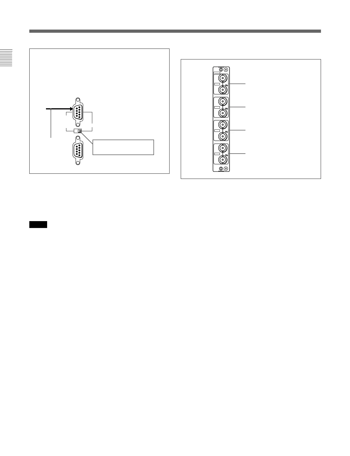
Y/G connectors (BNC)
PB/B connectors (BNC)
PR/R connectors (BNC)
SYNC connectors (BNC)
129X
IN
OUT
IN
OUT
IN
OUT
IN
OUT
ANALOG
Y/G
P
B
/B
P
R
/R
SYNC
7 Analog input/output connectors (BKM-129X)
RGB signals or component signals (Y/PB/PR) can be
fed in the IN connectors. The type of signal applied to
each connector is set with the INPUT CONFIG menu.
The OUT connectors are used for loop-through output
of the input signal.
For information about the INPUT CONFIG menu, see “ [C]
Setting the Input Configuration — INPUT CONFIG Menu”
on page 35(E).
8 AUDIO IN/OUT (input/output) jacks (BVM-
D9H5U/D9H5E/D9H5A only)
Connects to the audio output jacks of the VCR or
microphone amplifier. The monitor is equipped with
three input and output jacks. You can obtain the loop-
through output from the OUT jacks.