2
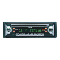
XR-CA430X/CA440
TABLE OF CONTENTS
1. GENERAL ................................................................... 3
2. DISASSEMBLY
2-1. Disassembly Flow ........................................................... 7
2-2. Mechanism Deck (MG-25L-136) ................................... 7
2-3. MAIN Board ................................................................... 8
2-4. Heat Sink (ISO)............................................................... 8
3. ASSEMBLY
3-1. Assembly Flow................................................................ 9
3-2. Housing ........................................................................... 10
3-3. Arm (Suction) ................................................................. 10
3-4. Lever (LDG-A)/(LDG-B) ............................................... 11
3-5. Gear (LDG-FT) ............................................................... 11
3-6. Guide (C) ......................................................................... 12
3-7. Mounting Position of Capstan/Reel Motor (M901) ....... 12
4. MECHANICAL ADJUSTMENTS ....................... 13
5. ELECTRICAL ADJUSTMENTS
Tape Deck Section .......................................................... 13
Tuner Section .................................................................. 13
6. DIAGRAMS
6-1. Note for Printed Wiring Boards and
Schematic Diagrams ....................................................... 14
6-2. Printed Wiring Board – MAIN Board – ......................... 18
6-3. Schematic Diagram – MAIN Board (1/3) – ................... 19
6-4. Schematic Diagram – MAIN Board (2/3) – ................... 20
6-5. Schematic Diagram – MAIN Board (3/3) – ................... 21
6-6. Printed Wiring Board – KEY Board –............................ 22
6-7. Schematic Diagram – KEY Board – .............................. 23
6-8. IC Pin Function Description ........................................... 24
7. EXPLODED VIEWS
7-1. Chassis Section ............................................................... 26
7-2. Front Panel Section ......................................................... 27
7-3. MAIN Board Section ...................................................... 28
7-4. Mechanism Deck Section (MG-25L-136)...................... 29
8. ELECTRICAL PARTS LIST ............................... 30
Notes on chip component replacement
• Never reuse a disconnected chip component.
• Notice that the minus side of a tantalum capacitor may be dam-
aged by heat.
Flexible Circuit Board Repairing
• Keep the temperature of the soldering iron around 270 ˚C dur-
ing repairing.
• Do not touch the soldering iron on the same conductor of the
circuit board (within 3 times).
• Be careful not to apply force on the conductor when soldering
or unsoldering.