XR-CA430X/CA440
7
SECTION 2
DISASSEMBLY
• This set can be disassembled in the order shown below.
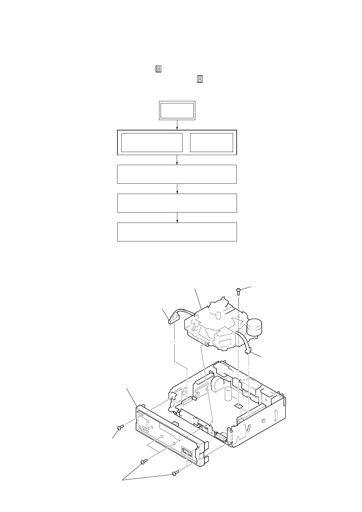
2-1. DISASSEMBLY FLOW
SET
2-2. MECHANISM DECK (MG-25L-136)
(Page 7)
COVER
(Note 3)
FRONT PANEL SECTION
(Note 3)
Note 1: The process described in can be performed in any order.
Note 2: Without completing the process described in , the next process can not be performed.
Note 3: Illustration of disassembly is omitted.
2-3. MAIN BOARD
(Page 8)
2-4. HEAT SINK (ISO)
(Page 8)
Note: Follow the disassembly procedure in the numerical order given.
2-2. MECHANISM DECK (MG-25L-136)
2
sub panel assy
1
screw (PTT2.6
×
6)
5
screw (PTT2.6
×
6
3
flexible board
(CNP301)
4
connector (CN351)
6
mechanism deck
(MG-25L-136)
1
four screws
(PTT2.6
×
6)