Do you have a question about the Sony CDX-CA710X and is the answer not in the manual?
Details on minimum continuous average power output and total harmonic distortion for US models.
Technical specs for the CD player section, including S/N ratio, frequency response, and wow/flutter.
FM and AM tuning ranges, intermediate frequencies, signal-to-noise ratios, and distortion.
Details on speaker outputs, impedance, and maximum power output.
Lists various outputs, inputs, tone controls, and loudness settings for the unit.
Guidelines for preventing electrostatic breakdown and proper handling of the optical pick-up block.
Precautions for checking laser diode emission, emphasizing safe viewing distances.
Advisories on reusing chip components and handling tantalum capacitors.
Information on recommended test discs for CD-R/CD-RW playback capability.
Critical warnings for safety-related components and general precautions.
Information on using unleaded solder, its characteristics, and handling precautions.
Instructions for connecting extension cables and setting up the service position for repair.
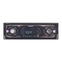
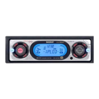
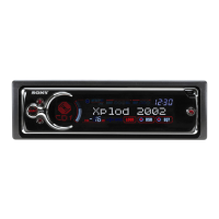
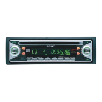
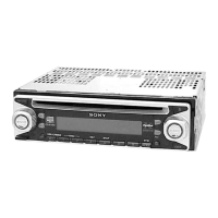
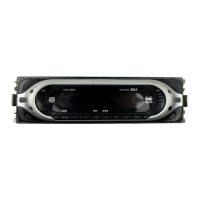
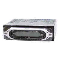
Identifies and describes the buttons and controls on the main unit and their functions.
Details on how to connect the unit to power and other components.
Explains the functionality and operation of the RM-X118 card remote commander.
Visual representation and explanation of all external connections for the unit.
How to connect for maintaining memory settings when the unit is off.
Important considerations and warnings for connecting speakers to the unit.
Step-by-step instructions and diagrams for disassembling the sub panel assembly.
Instructions for removing the CD mechanism block from the unit.
Steps for disassembling and removing the main board.
Procedure for removing the heat sink and MJ board.
Steps for disassembling the main chassis (T.U) assembly.
Instructions for removing the disc in board.
Steps for disassembling and removing the servo board.
Procedure for disassembling the shaft roller assembly, including parts and placement.
Steps for disassembling the floating block assembly, detailing springs and levers.
Instructions for removing the optical pick-up block and associated parts.
Detailed pin assignments and functions for IC303 (System Control).
Continued pin assignments and functions for various ICs.
A block diagram illustrating the signal flow and components within the CD section.
A block diagram showing the signal path and components for the tuner section.
Block diagram illustrating the signal flow for the display section, including key matrix and LCD drive.
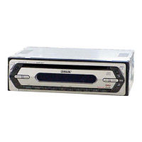
Diagram showing the physical layout and location of various circuit boards within the unit.
Printed wiring board layout for the CD mechanism section, showing component placement and traces.
Printed wiring board layouts for multiple boards including Servo, Disc In, Limit, Sub, and Motor Flexible.
Detailed schematic diagram for the CD mechanism section, showing component interconnections and signal paths.
Printed wiring board layout for the main section, detailing component placement.
Schematic diagram for the main section, covering power, voltage regulation, and volume control circuits.
Schematic diagram for the main section, detailing system control, bus interface, and reset circuits.
Printed wiring board layout for the relay section, showing component placement on the sub board.
Printed wiring board layout for the key section, detailing component placement for buttons and display.
Schematic diagram for the key section, showing connections for buttons, display, and rotary encoder.
Block diagram illustrating the internal functions and connections of IC1 on the servo board.
Block diagrams for IC2 (Servo Board) and IC301 (Main Board).
Block diagram illustrating the functions of IC201 on the main board, including power and protection circuits.
Block diagram for IC401 on the main board, detailing audio processing and equalizer functions.
Exploded view of the chassis assembly, showing all mechanical parts and their reference numbers.
Exploded view of the main board and associated components, including the MJ board and tuner unit.
Exploded view of the front panel assembly, showing buttons, display, and related parts.
Exploded view of the CD mechanism, showing chassis, springs, boards, and motor.
Further exploded view of the CD mechanism, detailing levers, gears, and springs.
Final exploded view of the CD mechanism, showing chassis, optical pick-up, and boards.
List of electrical parts including switches, diodes, LEDs, and some capacitors with their part numbers.
Detailed list of resistors, capacitors, switches, thermistor, tuner, and vibrator components.
List of capacitors, diodes, transistors, ferrite beads, ICs, jacks, and coils.
Comprehensive list of resistors, switches, and vibrator components.
List of capacitors, connectors, diodes, and ICs for MJ, Servo, and Sub boards.
List of miscellaneous parts, accessories like remote commander, and installation components.
Records the version history of the service manual, including dates and descriptions of revisions.
| Type | CD Receiver |
|---|---|
| CD Playback | Yes |
| MP3 Playback | Yes |
| WMA Playback | Yes |
| AAC Playback | Yes |
| USB Port | Yes |
| Bluetooth | No |
| Equalizer | Yes |
| AUX Input | Yes |
| Detachable Faceplate | Yes |
| Display Type | LCD |
| Preset EQ | Yes |
| Subwoofer Output | Yes |
| Max Power Output | 4 x 52 Watts |
| Tuner Bands | FM/AM |
| Preamp Voltage | 2 Volts |
| EQ Settings | 7-band EQ |