1
Ver 1.1 2003. 02
Model Name Using Similar Mechanism NEW
CD Drive Mechanism Type MG-393XA-121//Q
Optical Pick-up Name KSS-720A
SERVICE MANUAL
US Model
Canadian Model
CDX-CA700X
AEP Model
UK Model
CDX-CA700/CA700X
CDX-CA700/CA700X
AUDIO POWER SPECIFICATIONS (US Model)
POWER OUTPUT AND TOTAL HARMONIC DISTORTION
23.2 watts per channel minimum continuous average power into
4 ohms, 4 channels driven from 20 Hz to 20 kHz with no more
than 5% total harmonic distortion.
CD player section
Signal-to-noise ratio 90 dB
Frequency response 10 – 20,000 Hz
Wow and flutter Below measurable limit
Tuner section
FM
Tuning range 87.5 – 107.9 MHz (US, Canadian Model)
87.5 – 108.0 MHz (AEP, UK Model)
Antenna terminal External antenna connector
Intermediate frequency 10.7 MHz/450 kHz
Usable sensitivity 8 dBf
Selectivity 75 dB at 400 kHz
Signal-to-noise ratio 66 dB (stereo),
72 dB (mono)
Harmonic distortion at 1 kHz
0.6% (stereo),
0.3% (mono)
Separation 35 dB at 1 kHz
Frequency response 30 – 15,000 Hz
AM (US, Canadian Model)
Tuning range 530 – 1,710 kHz
Antenna terminal External antenna connector
Intermediate frequency 10.7 MHz/450 kHz
Sensitivity 30 µV
MW/LW (AEP, UK Model)
Tuning range MW : 531 – 1,602 kHz
LW : 153 – 279 kHz
Aerial terminal External aerial connector
Intermediate frequency 10.7 MHz/450 kHz
Sensitivity MW : 30 µV
LW : 40 µV
SPECIFICATIONS
Power amplifier section
Outputs Speaker outputs
(sure seal connectors)
Speaker impedance 4 – 8 ohms
Maximum power output 52 W × 4 (at 4 ohms) (US, Canadian Model)
50 W × 4 (at 4 ohms) (AEP, UK Model)
General
Outputs Audio outputs (front /rear)
Power antenna relay control terminal
Power amplifier control terminal
Inputs Telephone ATT control terminal
Illumination control terminal
BUS control input terminal
BUS audio input terminal
Remote controller input terminal
Antenna input terminal
Tone controls Bass ±10 dB at 62 Hz (US, Canadian Model)
Bass ±8 dB at 100 Hz (AEP, UK Model)
Treble ±10 dB at 16 kHz (US, Canadian Model)
Treble ±8 dB at 10 kHz (AEP, UK Model)
Loudness +8 dB at 100 Hz
+2 dB at 10 kHz
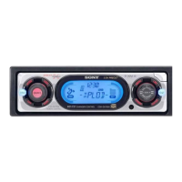
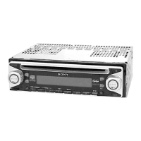
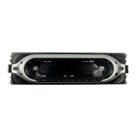
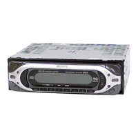
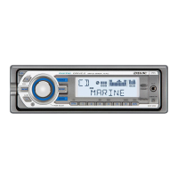
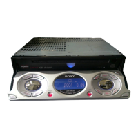
Photo: CDX-CA700
• The tuner and CD sections have no adjustments.
Sony Corporation
e Vehicle Company
Published by Sony Engineering Corporation
9-873-445-02
2003B0400-1
© 2003. 02
– Continued on next page –
FM/AM COMPACT DISC PLAYER
CDX-CA700X
FM/MW/LW COMPACT DISC PLAYER
CDX-CA700/CA700X
w
w
w
.
x
i
a
o
y
u
1
6
3
.
c
o
m
Q
Q
3
7
6
3
1
5
1
5
0
9
9
2
8
9
4
2
9
8
T
E
L
1
3
9
4
2
2
9
6
5
1
3
9
9
2
8
9
4
2
9
8
0
5
1
5
1
3
6
7
3
Q
Q
TEL 13942296513 QQ 376315150 892498299
TEL 13942296513 QQ 376315150 892498299
http://www.xiaoyu163.com
http://www.xiaoyu163.com