26
XR-CA430X/CA440
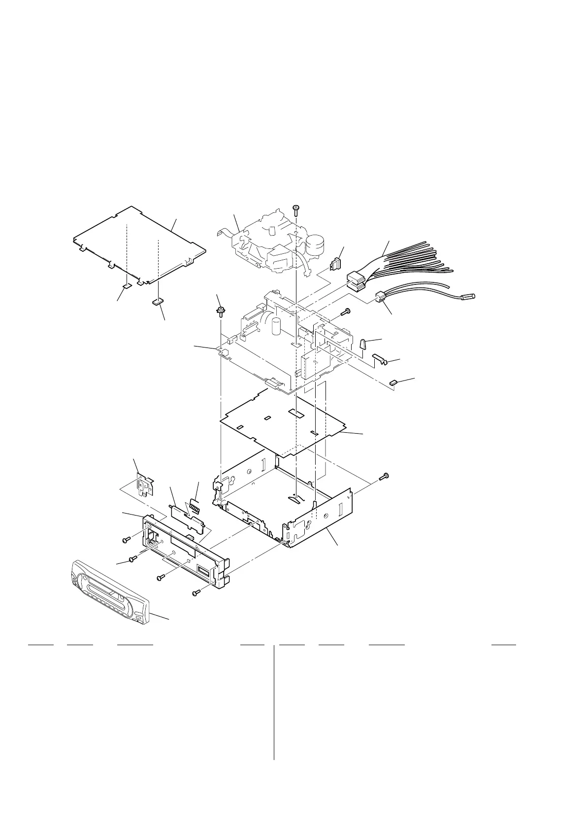
7-1. CHASSIS SECTION
SECTION 7
EXPLODED VIEWS
• Items marked “*” are not stocked since they
are seldom required for routine service. Some
delay should be anticipated when ordering
these items.
• The mechanical parts with no reference num-
ber in the exploded views are not supplied.
• Accessories are given in the last of the elec-
trical parts list.
NOTE:
• -XX and -X mean standardized parts, so they
may have some difference from the original
one.
• Color Indication of Appearance Parts
Example:
KNOB, BALANCE (WHITE) . . . (RED)
↑↑
Parts Color Cabinet's Color
Ref. No. Part No. Description Remark
Ref. No. Part No. Description Remark
1 3-042-244-11 SCREW (T)
2 3-224-862-04 PANEL, SUB
3 X-3370-437-3 LOCK ASSY
4 3-027-437-51 DOOR, CASSETTE
5 3-935-003-01 SPRING, TORSION
6 3-376-464-11 SCREW (+PTT 2.6X6), GROUND POINT
* 7 3-046-991-01 SPACER (COVER R)
* 8 3-046-990-01 SPACER (COVER L)
9 3-040-995-31 COVER
10 3-012-859-21 CAP (25), RUBBER
* 11 3-045-878-01 PLATE (TU), GROUND
* 12 3-045-877-02 CUSHION (TU)
* 13 3-033-846-02 INSULATED PLATE
14 3-009-813-61 CHASSIS
15 1-782-381-11 CORD (WITH CONNECTOR) (ISO P&S)
(POWER)
16 1-777-989-41 CORD (WITH CONNECTOR) (AMP REM/ATT)
F781 1-532-877-11 FUSE (BLADE TYPE) (AUTO FUSE) (10A/32V)
#1 7-685-792-09 SCREW +PTT 2.6X6 (S)
#3 7-685-794-09 SCREW +PTT 2.6X10 (S)
MG-25L-136
1
2
3
4
5
6
7
8
9
10
11
12
13
14
15
16
front panel section
main board section
#1
#1
#1
F781
#1
#3
#3