– 31 –
SECTION 4
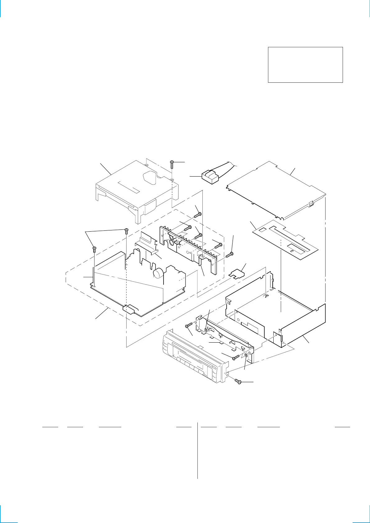
EXPLODED VIEWS
NOTE:
• The mechanical parts with no reference
number in the exploded views are not supplied.
• Items marked “*” are not stocked since
they are seldom required for routine service.
Some delay should be anticipated
when ordering these items.
• -XX and -X mean standardized parts, so
they may have some difference from the
original one.
• Color Indication of Appearance Parts
Example :
KNOB, BALANCE (WHITE) ... (RED)
Parts Color Cabinet’s Color
• Accessories and packing materials are
given in the last of this parts list.
The components identified by
mark ! or dotted line with mark.
! are critical for safety.
Replace only with part number
specified.
Ref. No. Part No. Description Remark
4-1. CHASSIS SECTION
N
N
Ref. No. Part No. Description Remark
MG-310-153
TU700
1
2
3
4
5
8
6
6
6
6
6
6
6
6
11
11
6
9
10
7
F901
* 1 3-034-437-01 COVER
2 3-376-464-11 SCREW (+PTT 2.6X6), GROUND POINT
* 3 A-3294-623-A MAIN BOARD, COMPLETE
* 4 3-034-438-01 BRACKET (IC)
* 5 3-034-441-01 HEAT SINK
6 7-685-793-09 SCREW +PTT 2.6X8 (S)
* 7 3-034-439-01 BRACKET (FRONT)
* 8 3-034-436-01 CHASSIS
* 9 3-034-455-01 SHEET (INSULATING)
10 1-776-207-31 CORD (WITH CONNECTOR) (POWER)
11 3-037-732-01 SPACER (WASHER)
F901 1-532-877-11 FUSE (BLADE TYPE) (AUTO FUSE) 10A
TU700 A-3220-689-A TUNER UNIT (TUX-010/2(E))