30
CX-JTD8
SECTION 5
ELECTRICAL ADJUSTMENTS
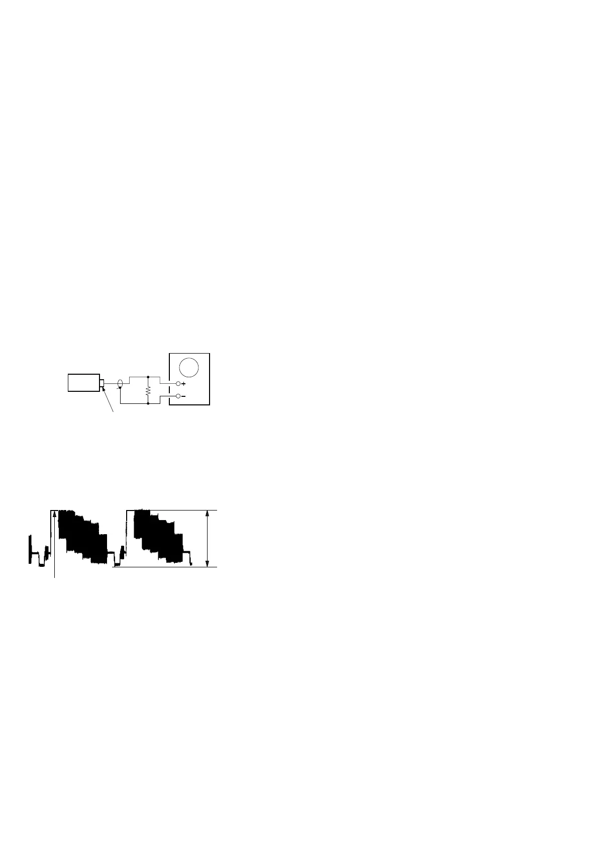
J802
VIDEO OUTPUT
75
Ω
Oscilloscope
set
1.00
±
0.05 Vp-p
(WHITE 100%)
Note:
1. VIDEO board is basically designed to operate without adjustment.
Therefore, check each item in order given.
2. Use DVD reference disc unless othermise indicated.
[DVD reference disc]
LUV-P01 (CD): PART No. 4-999-032-01
TDV-520CSO (DVD-SL): PART No. J-2501-236-A
TDV-540C (DVD-DL): PART No. J-2501-235-A
Note: Do not use exiting test disc for DVD.
3. Use an oscilloscope with more than 10MΩ impedance.
4. Clean the object lens by an applicator with neutral detergent when the
signal level is low than specified value with the following checks.
AUTO SERVO ADJUSTMENT
After parts related to the servo circuit (RF amplifier (IC001), DSP
(IC401), motor driver (IC501), EEPROM (IC903) so on) are re-
placed, re-adjusting the servo circuit is necessary. Select “ALL” at
“1. DRIVE AUTO ADJUSTMENT” (Refer to page 21 in TEST
MODE) and adjust DVD-SL (single layer), CD and DVD-DL (dual
layer).
Video Level Check (VIDEO BOARD)
Purpose
This adjustment is made to satisfy the NTSC standard, and if not
adjusted correctly, the brightness will be too large or small.
Procedure:
1. Connect oscilloscope to VIDEO output.
2. Load a DVD reference disc playback.
3. Check the video signal level is 1.00±0.05Vp-p.