Do you have a question about the Sony STR-K1500 - Receiver Component For Ht-ddw1500 and is the answer not in the manual?
| Preset Station Qty | 30 |
|---|---|
| Digital Sound Processor (DSP) | Yes |
| Frequency Response | 20Hz - 20kHz |
| Surround Sound | Dolby Digital, DTS |
| Tuner Bands | FM/AM |
| Tuning Range | FM: 87.5 - 108 MHz, AM: 530 - 1710 kHz |
| Connector Type | RCA |
| Width | 430 mm |
| Depth | 310 mm |
| Height | 157.5 mm |
Details power output and specifications for amplifier circuits.
Lists and specifies available digital input connections.
Details analog output connections and voltage levels.
Lists and specifies analog input connections.
Provides tuning range, antenna specifications, and intermediate frequency.
Details AM tuning range, antenna, and intermediate frequency.
Covers power requirements, consumption, dimensions, and mass.
Specifies video and component video input/output formats.
Explains model identification and area code variations.
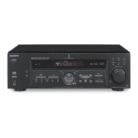
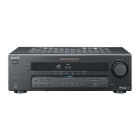
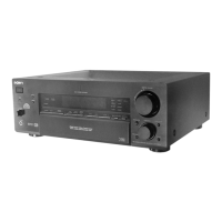
Describes front panel buttons, knobs, and their functions.
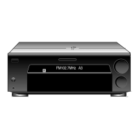
Details the meaning of various indicators on the front display.
Explains indicators showing playback channel status.
Illustrates and describes rear panel input/output terminals.
Explains how to use the remote control for operation.
Resets all preset contents to default settings.
Allows selection between 9 kHz and 10 kHz AM tuning steps.
Tests all fluorescent display segments for proper operation.
Clears preset sound field settings before client return.
Displays the receiver's model name, destination, and software version.
Verifies the functionality of each button on the unit.
Allows changing the common mode between AV 1 and AV 2.
Resets all preset contents to default settings for shipment.
Displays the protector status, indicating potential issues.
Initiates an automatic decoding test for all formats.
Controls the VACS system, allowing it to be turned off.
Swaps all modes, affecting system configuration.
Performs factory tests for DCAC DSP data and auto calibration.
Diagram showing the physical placement of internal circuit boards.
Illustrates typical waveforms for key test points.
High-level overview of the main audio and signal processing paths.
Overview of the display driver and power supply circuits.
Layout diagram for the digital board's component side.
Layout diagram for the digital board's solder side.
Part 1 of the digital board's schematic diagram.
Part 2 of the digital board's schematic diagram.
Part 3 of the digital board's schematic diagram.
Part 4 of the digital board's schematic diagram.
Part 5 of the digital board's schematic diagram.
Layout diagram for the main board.
Part 1 of the main board's schematic diagram.
Part 2 of the main board's schematic diagram.
Part 3 of the main board's schematic diagram.
Layout diagrams for display and power boards.
Schematic diagrams for display and power boards.
Layout diagrams for standby and AC select boards.
Layout diagram for the speaker C/SB board.
Schematic diagrams for speaker C/SB, standby, AC select boards.
Layout diagrams for ADCC and Video 3 boards.
Schematic diagrams for ADCC and Video 3 boards.
Layout diagrams for video and headphone boards.
Schematic diagrams for video and headphone boards.
Layout diagrams for the HDMI board.
Schematic diagram for the HDMI board.
Functional block diagrams for key integrated circuits.
Detailed pinout and function descriptions for ICs.
Exploded view of the front panel assembly and its parts.
Exploded view of the main chassis and internal components.
List of electrical parts for the AC Select board.
List of electrical parts for the ADCC board.
Detailed list of all capacitors used in the unit.
List of all connectors and their part numbers.
List of all diodes used, including part numbers and types.
List of all ICs used, with part numbers and descriptions.
Detailed list of all resistors used in the unit.