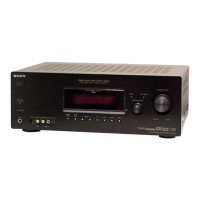
89
CX-JTD8
• MICON-KEY BOARD IC101 uPD780232GC-082-8BT (FRONT PANEL CONTROLLER)
Pin No. Pin Name I/O Description
1 VDD — Power supply terminal (+5V)
2 VSS — Ground terminal
3X1
I
System clock input terminal (5MHz)
4X2
O
System clock output terminal (5MHz)
5IC—Not used
6 RESET I
System reset signal input from the system controller
7 S-CLK I
Serial data transfer clock signal input from the system controller
8 S-IN O
Serial data output to the system controller
9 S-OUT I
Serial data input from the system controller
10
BASS-A I Jog dial pulse input from the rotary encoder (BASS) (A phase input)
11
BASS-B I Jog dial pulse input from the rotary encoder (BASS) (B phase input)
12
TRE/MID-A I Jog dial pulse input from the rotary encoder (TREBLE/MIDDLE) (A phase input)
13
TRE/MID-B I Jog dial pulse input from the rotary encoder (TREBLE/MIDDLE) (B phase input)
14
MULTI-A I Jog dial pulse input from the rotary encoder (MULTI JOG) (A phase input)
15
MULTI-B I Jog dial pulse input from the rotary encoder (MULTI JOG) (B phase input)
16
VOL-A I Jog dial pulse input from the rotary encoder (VOLUME) (A phase input)
17
VOL-B I Jog dial pulse input from the rotary encoder (VOLUME) (B phase input)
18 AVSS — Ground terminal
19 NC — Not used
20 to 22 KEY2 to KEY0
I Key input terminal (A/D input)
23 VSS — Ground terminal
24 AVDD — Power supply terminal (+5V)
25 VDD — Power supply terminal (+5V)
26 DVD-LED
O LED (DVD indicator) drive signal output terminal “L”: LED on
27 TUNER-LED
O LED (TUNER indicator) drive signal output terminal “L”: LED on
28 TAPE-LED
O LED (TAPE indicator) drive signal output terminal “L”: LED on
29 MD-LED
O LED (MD (VIDEO) indicator) drive signal output terminal “L”: LED on
30 I-BASS-LED
O LED (I-BASS indicator) drive signal output terminal “L”: LED on
31 HEAVY-LED
O LED (HEAVY indicator) drive signal output terminal “L”: LED on
32 VOCAL-LED
O LED (VOCAL indicator) drive signal output terminal “L”: LED on
33 SALSA-LED
O LED (SALSA indicator) drive signal output terminal “L”: LED on
34 MANUAL-LED
O LED (MANUAL indicator) drive signal output terminal “L”: LED on
35 HIP_HOP-LED
O LED (HIP HOP indicator) drive signal output terminal “L”: LED on
36 TECHNO-LED
O LED (TECHNO indicator) drive signal output terminal “L”: LED on
37 MULTI-LED
O LED drive signal output terminal “L”: LED on Not used
38 DISC1-LED
O LED drive signal output terminal “L”: LED on Not used
39 DISC2-LED
O LED drive signal output terminal “L”: LED on Not used
40 DISC3-LED
O LED drive signal output terminal “L”: LED on Not used
41 E-CLK — Not used
42 E-LAT — Not used
43 E-DAT — Not used
44 to 58
S1 to S14
O
Segment drive signal output to the fluorescent indicator tube
59 VDD — Power supply terminal (+5V)
60 V.LOAD
—
Power supply terminal (–25V) (for fluorescent indicator tube drive)
61 to 68
S15 to S22
O
Segment drive signal output to the fluorescent indicator tube
69 to 80
G12 to G1
O
Grid drive signal output to the fluorescent indicator tube