EasyManua.ls Logo

Sony DXC-637 - Service Information: PC Board Switch Functions; IE-47 and PR-209 Board Switches

Sony DXC-637
63 pages
Print Icon
To Next Page IconTo Next Page
To Previous Page IconTo Previous Page
Loading...
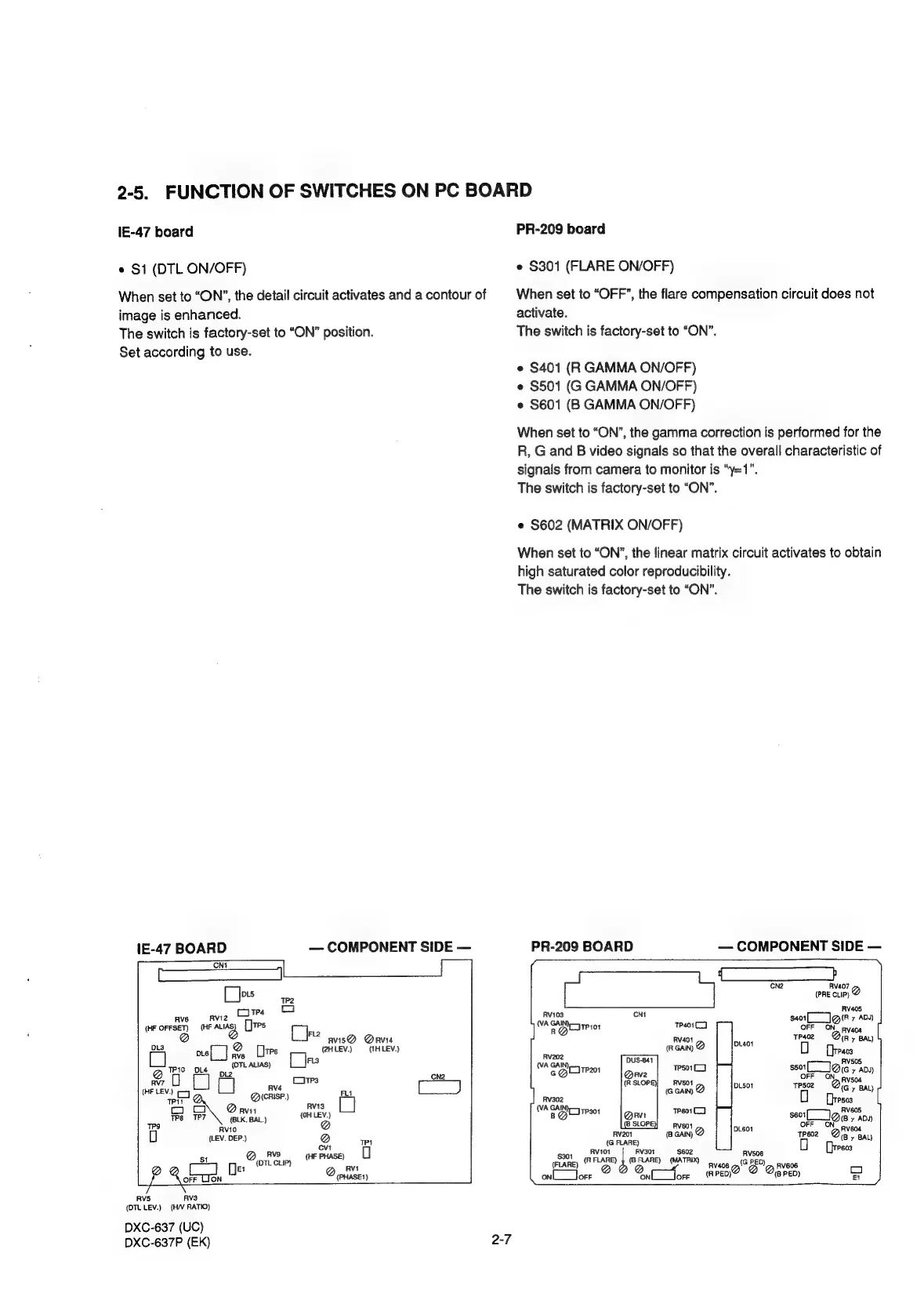
2-5.
FUNCTION
OF
SWITCHES
ON
PC
BOARD
lE-47
board
*
S1
(DTL
ON/OFF)
When
set
to
“ON”,
the
detail
circuit
activates
and
a
contour
of
image
is
enhanced.
The
switch
is
factory-set
to
“ON”
position.
Set
according
to
use.
1E-47
BOARD
—
COMPONENT
SIDE
—
CN1
a
ae
[J
DLS
1P2
or
©
RAV6
RVI2
[Je
(HF
OFFSET)
(HE
Aun
(tes
@
avis®
Davis
DLs
@
2HLEV.)
—
(1HLEV.)
ots[_]
eve
Ltrs
ite
iii:
bua
(OTL
ALIAS)
pi2
aie
Ne
le
LJ
aeaerts
RVS
HF
LEV.
:
aa
QrisP.)
Flt
RVI3
OW
@avn
We
=1P7
(BLK.
BAL)
(OH
LEV.)
ial
AviO
(LEV.
DEP.)
Q
Pi
cvt
o
$1
@__
Rvs
(HF
PHASE}
(OTL
CLIP)
ca
De:
@_AM
OFF
LION
(PHASE?)
RV5
AVS
(DTL
LEV.)
(H/V
RATIO)
DXC-637
(UC)
DXC-637P
(EK)
PR-209
board
e
S301
(FLARE
ON/OFF)
When
set
to
“OFF”,
the
flare
compensation
circuit
does
not
activate.
The
switch
is
factory-set
to
“ON”.
*
S401
(R
GAMMA
ON/OFF)
*
S501
(G
GAMMA
ON/OFF)
*
S601
(B
GAMMA
ON/OFF)
When
set
to
“ON”,
the
gamma
correction
is
performed
for
the
R,
G
and
B
video
signals
so
that
the
overall
characteristic
of
signals
from
camera
to
monitor
is
“y=1”.
The
switch
is
factory-set
to
“ON”.
e
S602
(MATRIX
ON/OFF)
When
set
to
“ON”,
the
linear
matrix
circuit
activates
to
obtain
high
saturated
color
reproducibility.
The
switch
is
factory-set
to
“ON”.
PR-209
BOARD
—
COMPONENT
SIDE
—
CN2
RV407
fa
an
.
RV405
AV103
cNt
$401
(Ry
ADY)
Se
RO
Trio
Test)
Cle
Pvaoa
Rv401
046i
tpaoz
=
Qin
BAL)
(RGAIN)
@
pact
RV202
FIVSOS
WA
eomtPa
Teso1l)
sso
101
y
ADJ)
pvsor
RV504
oan
@
DLSot
tesez
=
Qigy
Bay
Fv302
503
[
(VA
GAIN
yp
301
tPeo1
(J
RvV605
BQ
seo
10
y
ADA)
RV601
DL601
604
(8
GAIN)
@
trez
@
(G
FLARE)
(By
BAL)
soo
RVI
RV30t
$602
Rvs06
Pegs
(Flan)
(FLARE)
}
(GFLARE)
(MATRIX)
2"
5D
ae
=
onL__lorr
ofr
(RED)
(8
PED)
Ei