83
Specifications
Appendix
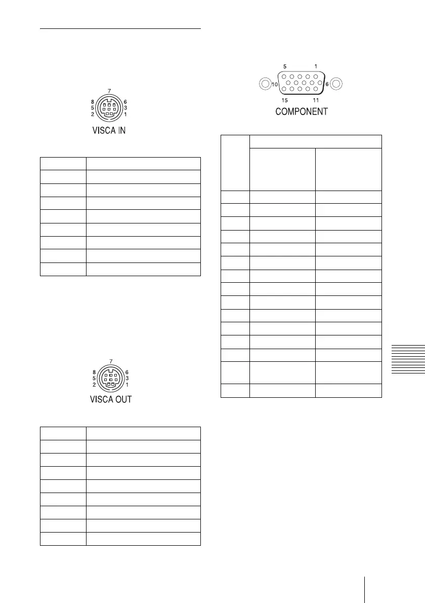
Pin assignments
VISCA IN connector (mini-DIN 8-pin,
female)
* The IR OUT function of pins 7 and 8 is
selectable with the BOTTOM switch on
the bottom of the camera.
VISCA OUT connector (mini DIN 8-
pin, female)
HD OUT COMPONENT connector (D-
sub, 15-pin)
Pin No. Function
1DTR IN
2DSR IN
3TXD IN
4 GND
5RXD IN
6 GND
7 IR OUT (R)*
8 IR OUT (L)*
Pin No. Function
1DTR OUT
2 DSR OUT
3 TXD OUT
4 GND
5 RXD OUT
6 GND
7 No connection
8 No Connection
Pin
No.
Function
At YPbPr
COMPONEN
T setting (at
SYNC)
At YPbPr
COMPONEN
T setting (at
VD)
1 Pr-OUT Pr-OUT
2 Y-OUT Y-OUT
3 Pb-OUT Pb-OUT
4 GND GND
5 GND GND
6 GND GND
7 GND GND
8 GND GND
9 No connection No connection
10 GND GND
11 GND GND
12 No connection No connection
13 HD-OUT HD-OUT
14 Tri-level SYNC-
OUT
Bi-level VD-
OUT
15 No connection No connection