HCD-CX4iP/CX5iP
10
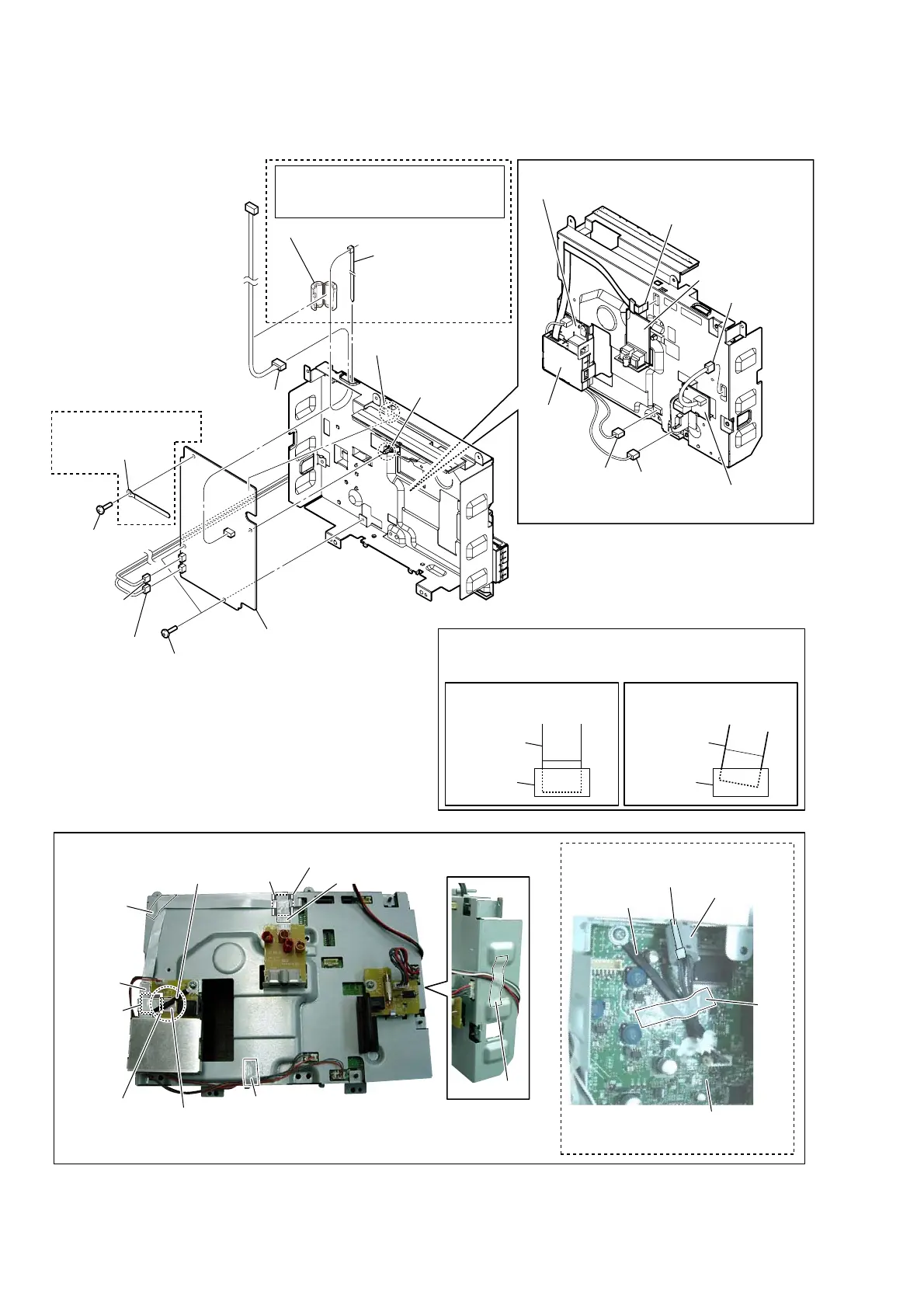
2-5. MAIN BOARD
– Rear side view –
– Front side view –
– Rear side view –
0 two screws
(BVTT3 u 6)
0 screw
(BVTT3 u 6)
qa coating clip (75)
coating clip (75)
qs spacer
(KGSL-2M-V0)
qd claw
qf MAIN board
1 connector
(CN301)
7 connector
(CN471)
9 connector
(CN702)
8 connector
(CN701)
2 connector
(CN690)
3 connector
(CN671)
4 flexible flat cable (7 core)
(CN1161)
AUDIO-JACK board
DC-JACK board
SP board
tuner block
5 Cut the binding
band (taiton).
binding band (taiton)
6 sleeve ferrite clamp
sleeve ferrite clamp
tape
tape
tape
Note 1:
In reassembling, use new binding
band (taiton) to fasten the clamp
same as before.
Note 2:
When you install the flat cable, please install them correctly.
There is a possibility that this machine damages when not
correctly installing it.
Insert is straight to the interior. Insert is incline
flat cable
connectorconnector
flat cable
OK NG
(US, Canadian)
(US, Canadian)
(US, Canadian, Taiwan)
tape
ferrite core
ferrite core
tape
tape
tape
MAIN board
coating clip
:ire settinJ
adhesive
tape (EMC)
adhesive tape (EMC)