HCD-DJ2i
63
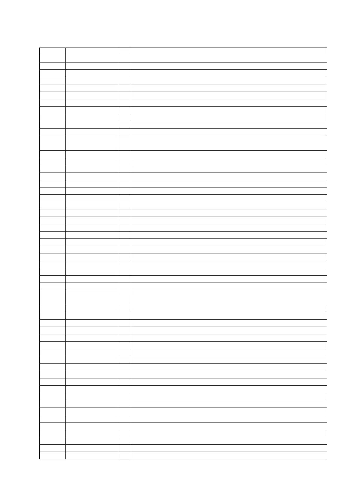
MAIN DIGITAL BOARD (2/2) IC100 R5F3640MDFAR (SYSTEM CONTROL)
Pin No. Pin Name I/O Description
1 ST-DIN I PLL serial data input from the tuner pack (FM/AM)
2 ST-CE O PLL chip enable signal output for the tuner pack (FM/AM)
3 ST-TUNED I TUNED detect signal input from the tuner pack (FM/AM)
4 SIRCS I SIRCS signal input from the remote control signal receiver IC
5 STBY RELAY O Main power ON/OFF control signal output (H: power ON)
6 IO-EXP-LAT O Serial latch signal output for the I/O expander IC
7 IO-EXP-CLK O Serial data output clock signal output for the I/O expander IC
8 BYTE — External data bus width select signal input (Connect to VSS in this set)
9 CNVSS — Processor mode select input (for test)
10 XC-IN I Sub system clock input (32.768 kHz)
11 XC-OUT O Sub system clock output (32.768 kHz)
12 RST I
System reset signal input from the RESET switch (L: reset)
After the power supply rises, L is input for several hundreds msec and then change to H
13 X-OUT O Main system clock output (5 MHz)
14 VSS — Ground
15 X-IN I Main system clock input (5 MHz)
16 VCC — Power supply pin (+3.3 V)
17 NMI I Non-maskable interrupt signal input (Fixed at H in this set)
18 IPOD1 DET I iPod 1 status detect signal input from the iPod 1 connector
19 SBSY I Subcode block sync detect signal input from the CD-MP3 processor IC
20 AC-CUT I AC cut ON/OFF detect signal input from the reset IC (L: AC cut ON)
21 IO-EXP-RST O Serial reset signal output for the I/O expander IC (L: reset)
22 IPOD2 RXD I UART serial reception data line input from the iPod 2 connector
23 IO-EXP-DO O Serial data output for the I/O expander IC
24 IPOD2 TXD O UART serial transmission data line output for the iPod 2 connector
25 TDA7448-DATA I/O Two-way serial data output for the 6ch volume control IC
26 TDA7448-CLK O Serial data transfer clock signal output for the 6ch volume control IC
27 R2A15216-DATA O Serial data output for the electronic volume IC
28 R2A15216-CLK O Serial data transfer clock signal output for the electronic volume IC
29 IPOD1 RXD I UART serial reception data line input from the iPod 1 connector
30 IPOD1 TXD O UART serial transmission data line output for the iPod 1 connector
31 PROG PORT O Serial data output for the fl ash programming connector
32 REG PROT I
Regulator short detect and fan current detect signal input/serial data input from the fl ash
programming connector
33 STANDBY LED O LED drive signal output for the standby indicator (H: standby LED ON)
34 I-USB CTS0 (DI) I Serial send control signal input from the USB control IC
35 O-USB TXD (SO) O UART serial transmission data line output for the USB control IC
36 I-USB RXD (SI) I UART serial reception data line input from the USB control IC
37 ML2252-NCR1 I Status signal input from the sound IC
38 O-USB RTS (DO) O Serial receive control output for the USB control IC
39 ML2252-NCR2 I Status signal input from the sound IC
40 ML2252-CLK O Serial data transfer clock signal output for the sound IC
41 PROTECTOR I Speaker protect detect signal input from the speaker protector circuit (H: speaker protect ON)
42 ML2252-DATA OUT O Serial data output for the sound IC
43 ML2252-WR O Write control signal output for the sound IC
44 ML2252-BUSY2 I Status signal input from the sound IC
45 ML2252-BUSY1 I Status signal input from the sound IC
46 LMR O Loading motor control signal output for the loading motor driver IC (for loading out)
47 LMF O Loading motor control signal output for the loading motor driver IC (for loading in)
48 CLOSE SW I Disc tray close position detect signal input (L: disc tray close)
49 OPEN SW I Disc tray open position detect signal input (L: disc tray open)
50 CD M-MUTE O Muting signal output for the loading motor drive IC
51 CD XRST O Reset signal output for the CD-MP3 processor IC (L: reset)
52 USB RST O Reset signal output for the USB control IC (L: reset)
53 CD BUS0 O Communication data bus line output for the CD-MP3 processor IC




 To Next Page