3
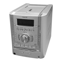
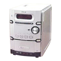
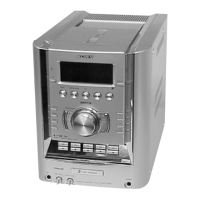
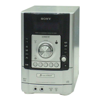
HCD-HP7
1. SERVICING NOTES ······················································· 4
2. GENERAL ·········································································· 6
3. DISASSEMBLY
3-1. Case (Side-L)(Side-R),
Tape Mechanism Deck (CMAL1Z234A) ······················ 9
3-2. Front Panel Section ······················································· 9
3-3. Panel Board ································································· 10
3-4. Back Panel Section ······················································ 10
3-5. MAIN Board ······························································· 11
3-6. PWR AMP Board, Power Transformer ······················· 11
3-7. CD Mechanism Deck (CDM69CH-K6BD71C)·········· 12
3-8. Base Unit Section ························································ 12
3-9. Base Unit (BU-K6BD71C) ········································· 13
3-10.BD Board····································································· 13
3-12.SW Board, Bracket (Top) Assy ··································· 14
3-13.CONNECTOR Board ·················································· 15
3-14.Motor (Stocker) Assy (Stocker)(M761) ······················ 15
3-15.Motor (Roller) Assy (Roller)(M781)··························· 16
3-16.Motor (Mode) Assy (Mode)(M771) ···························· 16
3-17.Rubber Roller (Slider) Assy ········································ 17
3-18.Timing Belt (Front/Rear)············································· 17
3-19.Cam (Gear) ·································································· 18
3-20.SENSOR Board ··························································· 18
4. ASSEMBLY
4-1. How to Install the Cam (Eject Lock) ···························· 18
4-2. How to Install the Cam (GEAR) ··································· 18
4-3. How to Install the Gear (MODE C) ······························ 19
4-4. How to Install the Gear (MODE CAM) ······················· 19
4-5. How to Install the Rotary Encoder (S702),
Gear (STOCKER COMMUNICATION) ····················· 20
4-6. How to Install the Stocker Assy ···································· 20
5. TEST MODE ···································································· 22
6. MECHANICAL ADJUSTMENTS ····························· 23
7. ELECTRICAL ADJUSTMENTS ······························· 24
8. DIAGRAMS······································································ 26
8-1. Block Diagram ···························································· 28
8-2. Printed Wiring Boards — BD Board —······················ 29
8-3. Schematic Diagram — BD Board — ·························· 30
8-4. Printed Wiring Boards — Changer Section — ··········· 31
8-5. Schematic Diagram — Changer Section — ················ 32
8-6. Printed Wiring Boards — Main Section —················· 33
8-7. Schematic Diagram — Main Section — ····················· 34
8-8. Printed Wiring Boards — Front Section — ················ 35
8-9. Schematic Diagram — Front Section —····················· 36
8-10.Printed Wiring Boards
— PWR AMP/Power Section —································· 37
8-11.Schematic Diagram
— PWR AMP/Power Section —································· 38
8-12.IC Block Diagrams ······················································ 39
8-13. IC Pin Function Description ······································· 42
9. EXPLODED VIEWS
9-1. Case, Top Panel Section ·············································· 44
9-2. Front Panel Section ····················································· 45
9-3. Chassis Section-1 ························································ 46
9-4. Chassis Section-2 ························································ 47
9-5. CD Mechanism Section-1 (CDM69CH-K6BD71C)··· 48
9-6. CD Mechanism Section-2 (CDM69CH-K6BD71C)··· 49
9-7. CD Mechanism Section-3 (CDM69CH-K6BD71C)··· 50
9-8. CD Mechanism Section-4 (CDM69CH-K6BD71C)··· 51
9-9. CD Mechanism Section-5 (CDM69CH-K6BD71C)··· 52
9-10.CD Mechanism Section-6 (CDM69CH-K6BD71C)··· 53
9-11.Optical Pick-up Section (KSM-213D) ························ 54
10.ELECTRICAL PARTS LIST ······································· 55
TABLE OF CONTENTS
Ver 1.1 2003.11