– 20 –
SECTION 5
ELECTRICAL ADJUSTMENTS
5-3. PRECAUTIONS FOR ADJUSTMENTS
1) When replacing the following parts, perform the adjustments
and checks with ® in the order shown in the following table.
Optical
BD (MD) board
Pick-up
IC171 D101 IC101, IC121, IC191
1. Temperature
compensation
× ®® ®
offset adjustment
2. Laser power
® ×× ®
adjustment
3. Traverse
®®× ®
adjustment
4. Focus bias
®®× ®
adjustment
5. Error rate check
®®× ®
2) Set the test mode when performing adjustments.
After completing the adjustments, exit the test mode.
3) Perform the adjustments in the order shown.
4) Use the following tools and measuring devices.
• Test disc (CD) TDYS-1 (Parts No. 4-963-646-01)
• Laser power meter LPM-8001 (Parts No. J-2501-046-A)
• Oscilloscope
• Digital voltmeter
• Thermometer
5) When observing several signals on the oscilloscope, etc., make
sure that VC and GND do not connect inside the oscilloscope.
(VC and GND will become short-circuited)
5-4. Creating MO Continuously Recorded Disc
* This disc is used in focus bias adjustment and error rate check.
The following describes how to create a MO continuous record-
ing disc.
1. Set the test mode.
2. Insert a MO disc (blank disc) commercially available.
3. Turning the MULTI JOG dial and display “CREC MODE”.
4. Press the ENTER/YES key and display “CREC IN”.
5. Press the ENTER/YES key again to display “CREC MID”.
“CREC (0300)” is displayed for a moment and recording starts.
6. Complete recording within 5 minutes.
7. Press the EDIT/NO key and stop recording.
8. Press the § (MD) key and remove the MO disc.
The above has been how to create a continuous recording data for
the focus bias adjustment and error rate check.
Note:
• Be careful not to apply vibration during continuous recording.
Note:
Be sure to connect all wires (including FFC) in the MD
section before applying power or ICs may be damaged.
MD SECTION
5-1. PRECAUTIONS FOR CHECKING LASER DI-
ODE EMISSION
To check the emission of the laser diode during adjustments,
never view directly from the top as this may lose your eye-
sight.
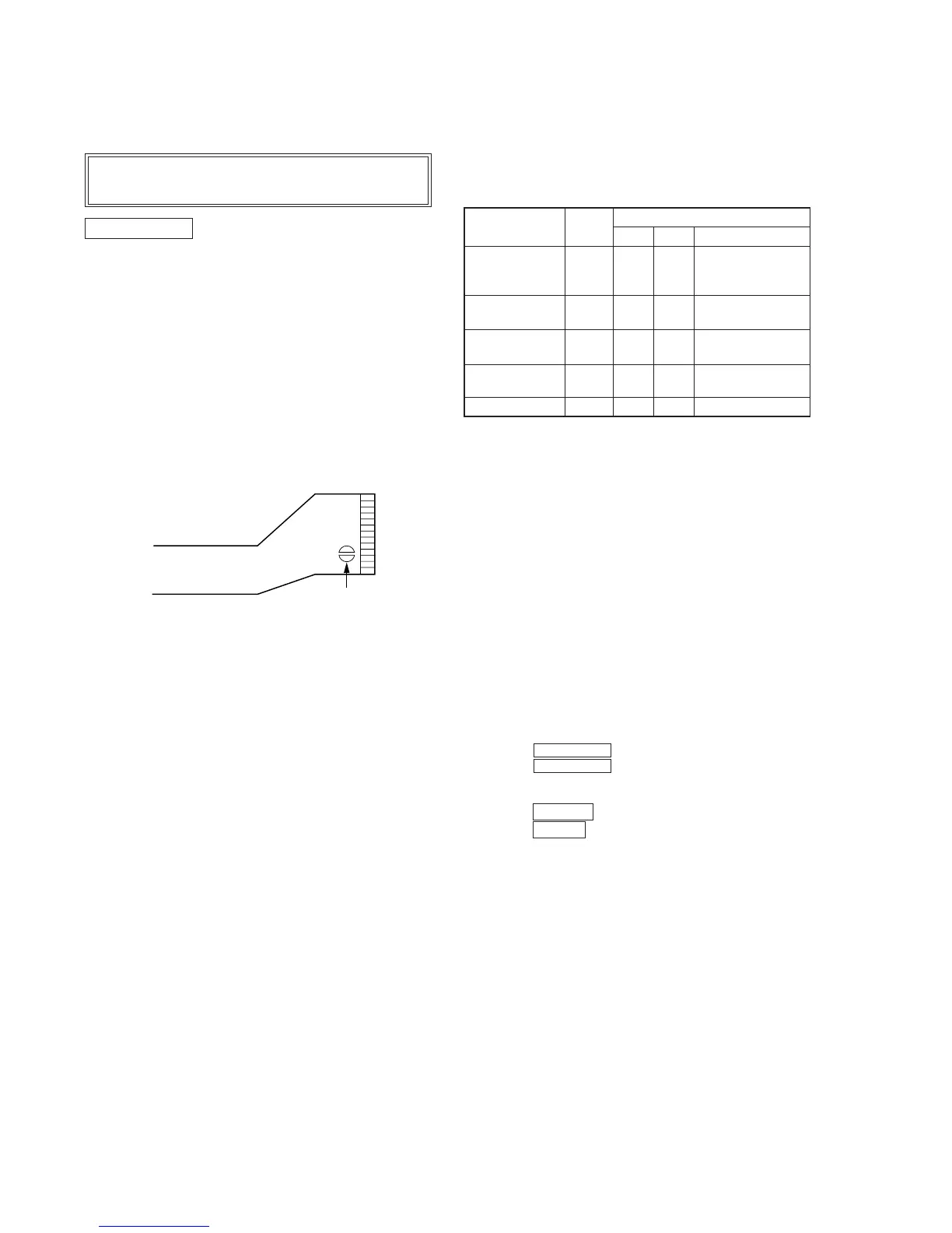
5-2. PRECAUTIONS FOR USE OF OPTICAL PICK-
UP (KMS-210A)
As the laser diode in the optical pick-up is easily damaged by
static electricity, solder the laser tap of the flexible board when
using it.
Before disconnecting the connector, desolder first. Before con-
necting the connector, be careful not to remove the solder.
Also tale adequate measures to prevent damage by static elec-
tricity. Handle the flexible board with care as it breaks easily.
Optical pick-up flexible board
Laser tap