– 25 –
TUNER SECTION
Precaution in Repairing
Note : As a front-end (FE1) is difficult to repair if faulty, replace it
with new one.
• Abbreviation
EA : Saudi Arabia
MY : Malaysia
SP :Singapore
HK : Hong Kong
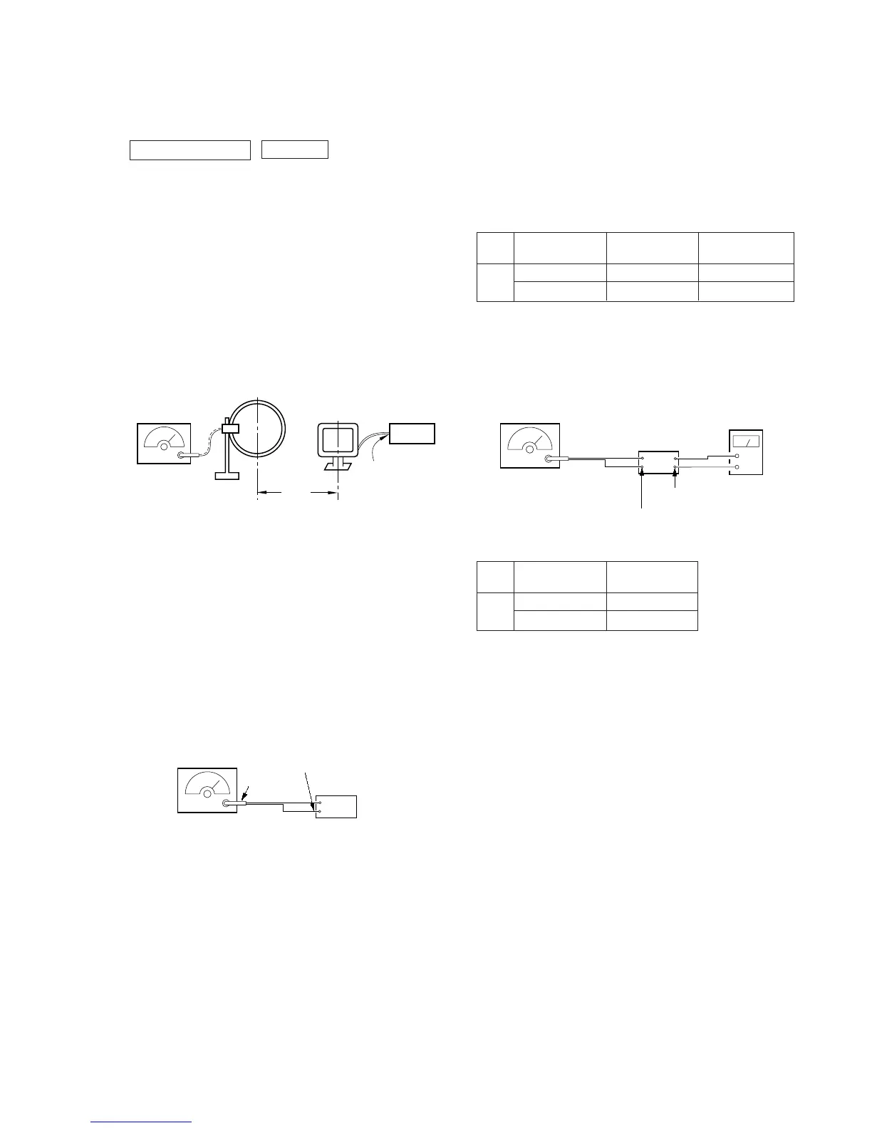
AM Tuned Level Adjustment
Note : FM Tuned Level Adjustment Should be performed after this
AM Tuned Level Adjustment.
Setting :
Band : AM or MW
0 dB=1µV
Procedure :
1. Set loop antenna A so that the loop antenna B input level be-
comes 50 dBµ (0.32 mV)
2. Tune the set to 999 kHz (at 9 kHz step) or 1,050 kHz (at 10 kHz
step).
3. Adjust RV41 so that the TUNED indicator goes on.
Adjustment Location : TCB board (see page 26)
FM Tuned Level Adjustment
Note : This adjustment should be performed after the AM Tuned
Level Adjustment.
Setting :
Band : FM
set
FM ANTENNA terminal (TM1)
FM RF stereo signal
generator
Carrier frequency : 98 MHz
Modulation : 1 kHz, 75 kHz deviation (100%)
Output level : 25 dB
µ
(0.018 mV)
75
Ω
coaxial
Procedure :
1. Tune the set to 98 MHz
2. Adjust RV42 so that the TUNED indicator goes on.
Adjustment Location : TCB board (see page 26)
SW OSC Voltage Adjustment (EA, MY, SP, HK model)
Setting :
Band : SW
Procedure :
1. Connect digital voltmeter to diode D1 center lead and ground.
2. Adjust for a following value reading on digital voltmeter.
Set frequency
Adjustment Reading on
part digital voltmeter
SW
5.95 MHz T2 1.2 Vdc
17.9 MHz CV2 8.5 Vdc
Adjustment Location : TCB board (see page 26)
SW Tracking Adjustment (EA, MY, SP, HK model)
Setting :
Band : SW
Procedure :
Adjust for maximum reading on level meter.
Set frequency
Adjustment
part
SW
7 MHz T1
17 MHz CV1
• Repeat the procedures is each adjustment several times, and the
OSC voltage and tracking adjustment should be finally done by
the trimmer capacitors.
Adjustment Location : TCB board (see page 26)
AM RF signal
generator
loop antenna A
set
loop antenna B
60 cm
AM ANTENNA
terminal (TM1)
30% amplitude
modulation by
400 Hz signal
Carrier frequency: 999 kHz (at 9 kHz step)
1,050 kHz (at 10 kHz step)