EasyManua.ls Logo

Sony ICD-UX71 User Manual

Sony ICD-UX71
42 pages
To Next Page IconTo Next Page
Page #1 background imageLoading...
Page #1 background image
SERVICE MANUAL
Sony Corporation
Audio&Video Business Group
Published by Sony Techno Create Corporation
ICD-UX71/UX71F/UX81/
UX81F/UX91F
SPECIFICATIONS
IC RECORDER
9-889-311-01
2008J04-1
©
2008.10
AEP Model
ICD-UX71/UX71F/UX81/UX81F
E Model
Chinese Model
ICD-UX71F/UX81F/UX91F
Latin American Model
ICD-UX71/UX71F/UX81/UX81F
Ver. 1.0 2008.10
Photo: ICD-UX71
IC recorder section
Capacity (User available capacity)
ICD-UX71/UX71F:
1 GB (approx. 986 MB =1,034,354,688 Byte)
ICD-UX81/UX81F:
2 GB (approx. 1.92 GB =2,072,313,856 Byte)
ICD-UX91F:
4 GB (approx. 3.86 GB =4,147,806,208 Byte)
A part of the memory capacity is used as a
management area.
Recording time*
1
ICD-UX71/UX71F
ST mode STSP mode STLP mode
11 hr. 55 min. 17 hr. 55 min. 47 hr. 50 min.
SP mode LP mode
71 hr. 45 min. 287 hr. 15 min.
ICD-UX81/UX81F
ST mode STSP mode STLP mode
23 hr. 55 min. 35 hr. 55 min. 95 hr. 55 min.
SP mode LP mode
143 hr. 50 min. 575 hr. 35 min.
ICD-UX91F
ST mode STSP mode STLP mode
47 hr. 55 min. 72 hr. 192 hr.
SP mode LP mode
288 hr. 1152 hr. 5 min.
(hr. : hours/min. : minutes)
*
1
When you are going to record continuously
for a long time, you may have to replace
the battery with a new one in the midst of
recording.
Frequency range
z
ST : 40 Hz - 20,000 Hz
z
STSP : 40 Hz - 15,000 Hz
z
STLP : 60 Hz - 7,500 Hz
z
SP : 60 Hz - 10,000 Hz
z
LP : 60 Hz - 3,400 Hz
Bit rates and sampling frequencies for
MP3 les*
2
Bit rate: 32 - 320 kbps, VBR
Sampling frequencies: 16/22.05/24/32/44.1/
48 kHz
*
2
The playback of MP3 les recorded using the
IC recorder is also supported.
Not all encoders are supported.
Bit rate and sampling frequencies*
3
for
WMA les
Bit rate: 32 - 192 kbps*
4
, VBR
Sampling frequencies: 44.1 kHz
*
3
WMA Ver. 8 Class2A is compatible, however,
MBR (Multi Bit Rate), Lossless, Professional,
and Voice are not supported.
*
4
The NoiseSubstitution function is not
supported, therefore, playback becomes
simple playback with 32 kbps bit rate.
FM radio section
Frequency range
87.5 - 108 MHz
IF 150 kHz
Antenna
Headphone cord antenna
General
Speaker
Approx. 10 mm dia.
Power output
90 mW
Input/Output
z
Microphone jack (minijack, stereo)
input for plug in power, minimum input
level 0.9 mV, 3 kilohms or lower impedance
microphone
z
Headphone jack (minijack, stereo)
output for 8 - 300 ohms headphones
z
USB connector
– High-Speed USB compatible
Playback speed control (DPC)
+100% to –50% (MP3)
0% to –50% (WMA)
Power requirements
One NH-AAA rechargeable battery (supplied):
1.2 V DC
One LR03 (size AAA) alkaline battery (not
supplied): 1.5 V DC
Operating temperature
5˚C - 35˚C
– Continued on next page –
Question and Answer IconNeed help?

Do you have a question about the Sony ICD-UX71 and is the answer not in the manual?

Sony ICD-UX71 Specifications

General IconGeneral
Frequency range40 - 20000 Hz
Recording modesLong Play (LP), Standard Play (SP), Stereo (ST)
Maximum recording time4.83 h
File typemp3
Battery typeAAA
Dimensions (WxDxH)34.4 x 13.4 x 99 mm
Compatible operating systemsWindows Vista/XP MediaCenter SP2/XP Professional SP2/XP Home Edition SP2/2000 Professional SP4, Mac OS X
Internal memory1024 MB
DC-in jackYes
Headphone out1
Battery life (max)34 h
Recording battery life17 h

Summary

Device Specifications

Recorder and Audio Specifications

Details IC recorder capacity, recording times, frequency ranges, and MP3/WMA bit rates.

Radio and General Features

Covers FM radio specifications, antenna, speaker, power output, input/output ports, and operating temperature.

Power Supply Details

Lists power requirements including rechargeable and alkaline battery types.

Component Handling and Notes

Product Dimensions and Weight

Provides physical dimensions and weight of the device as per JEITA standards.

Supplied Accessories List

Lists all items included with the IC recorder package.

Repair and Solder Precautions

Offers critical notes on chip component replacement, flexible circuit board repair, and unleaded solder.

General Device Operation

Parts and Controls Identification

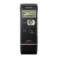
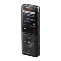
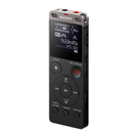
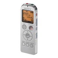
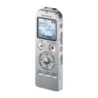
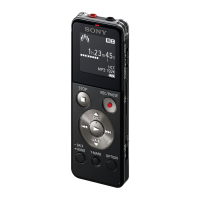
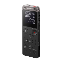
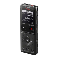
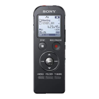
Identifies and locates all external parts and controls of the IC recorder.

Display Window Information

Explains the meaning of various indicators and icons shown on the device's display.

Control Button Usage Guide

Provides instructions on how to use the main control buttons for navigation and functions.

Display Indicators

Battery and Recording Time Indicators

Describes indicators for battery status, charging, and remaining recording time.

FM Radio Display Modes

Explains the display information shown when the FM radio function is active.

Disassembly Procedures

USB Cover Removal

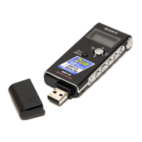
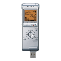
Step-by-step instructions for safely removing the USB cover.

Case Assembly Disassembly

Detailed steps for disassembling the main case assembly, including cautions.

Board Removal

Instructions for removing the audio and main boards from the unit.

Test Mode Functions

Test Mode Entry and Exit

Procedures for entering and exiting the device's service test mode.

Test Mode Menu Operations

Overview of the test mode menu and how to navigate its options.

Key and Function Tests

Functions for checking key input, version, loopback, and microphone calibration.

System Test Functions

Tests for beep, LCD contrast, RTC, battery, VBUS, menu initialization, and sleep mode.

System Diagrams

Main Section Block Diagram

Illustrates the overall system architecture of the main section.

Power and Display Block Diagram

Shows the block diagram for the power supply and display sections.

Printed Wiring Boards

Audio Section Component Layout

Diagram showing the placement of components on the audio circuit board.

Main Section Component Layout

Diagram showing the placement of components on the main circuit board.

Audio Circuit Schematics

Audio Section Schematic (1/3)

First part of the audio circuit schematic, detailing component interconnections.

Audio Section Schematic (2/3)

Second part of the audio circuit schematic, showing further circuit details.

Audio Section Schematic (3/3)

Final part of the audio circuit schematic, completing the circuit diagrams.

Main Circuit Schematics

Main Section Schematic (1/3)

First part of the main circuit schematic, illustrating core system connections.

Main Section Schematic (2/3)

Second part of the main circuit schematic, detailing additional system wiring.

Main Section Schematic (3/3)

Final part of the main circuit schematic, completing the system circuit diagrams.

IC Block Diagrams

Core IC Block Diagrams

Block diagrams for key integrated circuits like IC1002, IC1003, IC1004, IC2002, IC2004.

Additional IC Block Diagrams

Block diagrams for IC2003, IC2005, IC2013, IC3000, IC5003.

IC Pinout Descriptions

IC1001 Pinout Description

Details the function of each pin for the IC1001 audio codec.

IC5001 Pinout Description

Comprehensive pinout description for the IC5001 system control IC.

Exploded Views

Case Front Section Exploded View

Exploded view illustrating the components of the front case section.

Main Board Section Exploded View

Exploded view showing the assembly of the main board and its parts.

Case Rear Section Exploded View

Exploded view detailing the components of the rear case section.

Audio Board Section Exploded View

Exploded view illustrating the assembly of the audio board and its components.

Electrical Parts List

Passive Components List

Lists capacitors, diodes, resistors, coils, ferrite beads, and filters with specifications.

Active Components and Modules

Lists ICs, transistors, switches, connectors, and audio board components.

Main Board and Miscellaneous Parts

Lists main board components, network resistors, and other miscellaneous parts.

Accessories

Included Accessories List

Lists all accessories supplied with the device, including headphones, cables, and manuals.

Related product manuals