EasyManua.ls Logo

Sony LT10 Series User Manual

Sony LT10 Series
80 pages
To Next Page IconTo Next Page
Page #1 background imageLoading...
Page #1 background image
41
English
1. Note to users ............................................................ 42
1-1. General precautions........................................... 42
1-2. Handling instructions.......................................... 42
1-3. Cautions on operation ........................................ 43
1-4. Instructions for connecting to
the measuring unit ............................. 43
2. Summary .................................................................. 44
2-1. Features ............................................................. 44
2-2. System structure ................................................ 45
3. Connecting and installating .................................... 46
3-1. Connecting the cables ....................................... 46
3-2. Installing the display unit .................................... 46
4. Name and function of each part ............................. 47
4-1. Front panel ........................................................ 47
4-2. Rear panel ......................................................... 49
4-3. Function description ........................................... 50
5. Operation .................................................................. 52
5-1. Initial settings ..................................................... 52
5-2. Various settings ................................................. 56
6. Terminals I/O ............................................................ 60
6-1. Connector pin assignment ................................. 60
6-2. I/O circuitry ......................................................... 61
6-3. Signal timing ...................................................... 62
Contents
7. BCD output (only BCD model) ................................ 63
7-1. Connector pin assignment ................................. 63
7-2. I/O timing............................................................ 65
7-3. Interface cable ................................................... 66
7-4. Connection circuit .............................................. 67
8. RS-232C Interface (only RS-232C model) .............. 68
8-1. Terminal pin assignment .................................... 68
8-2. Connecting P40 digital printer ............................ 68
8-3. Connecting a personal computer ....................... 69
8-4. RS-232C Interface ............................................. 69
8-5. EXT. IN circuit .................................................... 70
8-6. Output ................................................................ 70
8-7. Commands......................................................... 71
9. Alarm display/output ............................................... 74
10. Specifications .......................................................... 75
11. Troubleshooting ...................................................... 79
Table of Contents

Questions and Answers:

Sony LT10 Series Specifications

General IconGeneral
Display TechnologyLCD
Aspect Ratio16:9
Brightness250 cd/m²
Response Time5ms
Native Resolution1920 x 1080
Resolution1920 x 1080
Contrast Ratio1000:1
Color Gamut72% NTSC

Summary

Note to users

1-1. General precautions

General precautions for using Sony Manufacturing Systems Corporation products to ensure proper use.

1-2. Handling instructions

Instructions on handling the device, including precautions against static electricity and AC adapter usage.

1-3. Cautions on operation

Cautions regarding key operations, I/O connections, and environmental conditions to prevent malfunctions.

1-4. Instructions for connecting to the measuring unit

Procedure for connecting the LT10/LT11 display unit to a DT series measuring probe and initialization.

Summary

2-1. Features

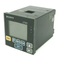
Description of the LT10/LT11 digital display unit's features, including compact size, connectivity, resolution, and measurement capabilities.

2-2. System structure

Diagram and explanation of the system structure, showing connections between the display unit, probes, PLC, computer, and printer.

Connecting and installing

3-1. Connecting the cables

Instructions for securing connecting cables and ensuring power is off before connecting/disconnecting the measuring unit.

3-2. Installing the display unit

Steps for mounting the display unit into a panel, including cut-out dimensions and counter stopper attachment.

Name and function of each part

4-1. Front panel

Description of the controls and indicators on the front panel of the 1 CH and 2 CH input models.

Main display

Explanation of the main display, preset status indicator, peak-hold indicator, and selected channel indicator.

Selected channel indicator (2 channel model)

Details on selecting channels A, B, or A+B for display and calculation in 2 channel models.

4-2. Rear panel

Overview of the rear panel terminals for 1-channel and 2-channel models, detailing their functions and connections.

4-3. Function description

Describes reset key operation, preset functions, result evaluation, and peak-hold function for the display unit.

Operation

5-1. Initial settings

Details on performing standard initialization and changing settings like inches/mm and other initial parameters.

5-1-1. Basic settings

Steps for setting the display, resolution, and direction for channel A and channel B on 2 channel models.

5-1-2. BCD model

Settings specific to the BCD model, including BCD logic and output format.

5-1-3. RS-232C model

Settings for the RS-232C model, covering output data format, signalling rate, data length, and stop-bit.

5-2. Various settings

Various settings for the display unit, including preset values, measuring modes, and comparator values.

Terminals I/O

6-1. Connector pin assignment

Detailed pin assignment for the rear panel terminals of the display unit for 1 CH and 2 CH models.

6-2. I/O circuitry

Explains the I/O circuitry for Go/No Go output, start/hold input, reset/recall input, and main DC power.

6-3. Signal timing

Diagrams and explanations of signal timing for Start/Reset input and Result evaluation output.

BCD output (only BCD model)

7-1. Connector pin assignment

Pin assignment details for the BCD connector, including signals and connectors to procure.

7-2. I/O timing

Timing diagrams for data, DRQ input, and READ output, and DRQ display/output hold feature.

7-3. Interface cable

Guidelines for using a shielded cable for interface connection and instructions for assembling the provided plug.

7-4. Connection circuit

Diagrams illustrating output circuits and input circuits (DRQ, TTL level) for connecting external devices.

RS-232C Interface (only RS-232C model)

8-1. Terminal pin assignment

Pin assignment for the RS-232C and EXT. IN terminals on the rear panel of the display unit.

8-3. Connecting a personal computer

Instructions and diagrams for connecting a personal computer using DZ252 and DZ253A RS-232C cables.

8-4. RS-232C Interface

Details on RS-232C signals, data parameters, and electrical specifications for the interface.

8-5. EXT. IN circuit

Explanation of the TTL level input circuit for the EXT.IN terminal.

8-6. Output

Describes four methods for outputting measured data via RS-232C, using EXT.IN terminal inputs.

8-7. Commands

Lists and explains ASCII commands for controlling the display unit and outputting data via RS-232C.

Alarm display/output

Specifications

Accessories

Instruction Manual

Manual for the digital display unit.

Counter stopper

Included accessory for mounting the display unit.

BCD output connector plug

Connector plug for BCD output models.

Options

Digital printer

Optional digital printer (P40) for printing measured values.

Connector cable for personal computer

Cables for connecting to a personal computer (9-pin and 25-pin Dsub).

Foot switch

Optional foot switch for controlling the unit.

Dimentions

Counter stopper

Dimensional drawings and specifications for the counter stopper accessory.

Cut out Opening

Dimensions for the panel cut-out required for installing the display unit.

Troubleshooting

The power cannot be turned on.

Steps to take when the unit does not turn on, including power cycling and cable checks.

Error is displayed (Alarm)

Troubleshooting steps for when an "Error" message is displayed, including probe issues and resetting.

Channel display is (Alarm)

Troubleshooting for channel display alarms, checking probe connection, and reset procedures.

Fifth digit is "F"

Solution for the "F" display, typically indicating an overflow or preset value issue.

No counting

Steps to resolve issues where the unit is not counting, involving power cycling.

Erroneous counting.

Checks for erroneous counting, including grounding, noise, and power voltage.

Accuracy cannot be obtained

Steps to take when accuracy cannot be obtained, checking for mechanical issues and temperature differences.

Cleaning

Instructions for cleaning the display and casing using dry cloth or diluted neutral detergent.

Related product manuals