16
MV-700HR
3. INVERTER FREQUENCY CHECK
Setting:
Procedure:
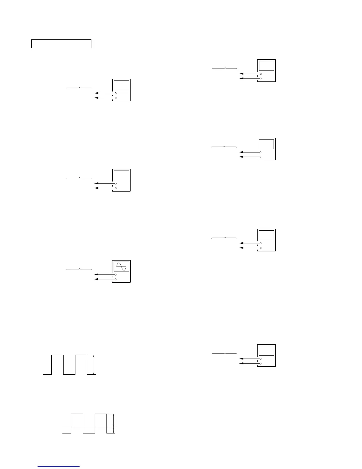
1. Connect a frequency counter to the TP434 and TP388 (GND)
on the MONITOR board.
2. Check that the value of frequency counter is 51 kHz ±2.5 kHz.
4. OSD DOT CLOCK CHECK
Setting:
Procedure:
1. Connect a frequency counter (high impedance) to the TP751
and TP753 (GND) on the MONITOR board.
2. Press the [POWER] button to turn the power on.
3. Check that the value of frequency counter is 6.5 MHz ±0.2
MHz.
2. V-COM ADJUSTMENT
Setting:
Procedure:
– Voltage Set-up Adjustment –
1. Connect an oscilloscope to the TP917 and TP929 (GND) on
the MONITOR board.
2. Press the [POWER] button to turn the power on.
3. Enter the test mode, and enter the “2. FOR FACTORY” mode.
(refer to “SECTION 4. TEST MODE”)
4. Press the [S-MENU] button to display “Com Gain”.
5. Adjust by pressing the [VOLUME +]/[VOLUME --] buttons so
that the voltage of oscilloscope becomes 7.3 Vp-p ±0.1 V.
6. Press the [SOURCE] button and write the data to EEPROM
(IC403 on the MONITOR board).
– Waveform Position Set-up Adjustment –
7. Adjust the RV851 on the MONITOR board so that A value
of waveform becomes –3.0 V ±0.1 V.
MONITOR SECTION
1. PLL ADJUSTMENT
1-1. PLL Voltage Adjustment
Setting:
Procedure:
1. Connect a digital voltmeter to the TP802 and TP929 (GND)
on the MONITOR board.
2. Press the [POWER] button to turn the power on.
3. Adjust the RV801 on the MONITOR board so that the value
of digital voltmeter becomes 2.2 V ±0.15 V.
1-2. PLL Frequency Check
Setting:
Procedure:
1. Connect a frequency counter to the TP801 and TP929 (GND)
on the MONITOR board.
2. Press the [POWER] button to turn the power on.
3. Check that the value of frequency counter is 28.699 MHz ±1
kHz.
+
–
digital voltmete
MONITOR board
TP751
TP753 (GND)
5. NTSC SUB CARRIER CHECK
Setting:
Procedure:
1. Connect a frequency counter to the TP701 and TP703 (GND)
on the MONITOR board.
2. Press the [POWER] button to turn the power on.
3. In the normal mode, press the [SOURCE] button to select the
“VIDEO” mode.
4. Input NTSC video signal to the A/V INPUT jack (J1004 on
the MAIN board).
5. Check that the value of frequency counter is 3.579545 MHz
±100 Hz.
6. PAL SUB CARRIER CHECK
Setting:
Procedure:
1. Connect a frequency counter to the TP701 and TP703 (GND)
on the MONITOR board.
2. Press the [POWER] button to turn the power on.
3. In the normal mode, press the [SOURCE] button to select the
“VIDEO” mode.
4. Input PAL video signal to the A/V INPUT jack (J1004 on the
MAIN board).
5. Check that the value of frequency counter is 4.433619 MHz
±100 Hz.
+
–
frequency counte
 Loading...