17
MV-700HR
1 Contrast Level of Luminance Signal
Setting:
Procedure:
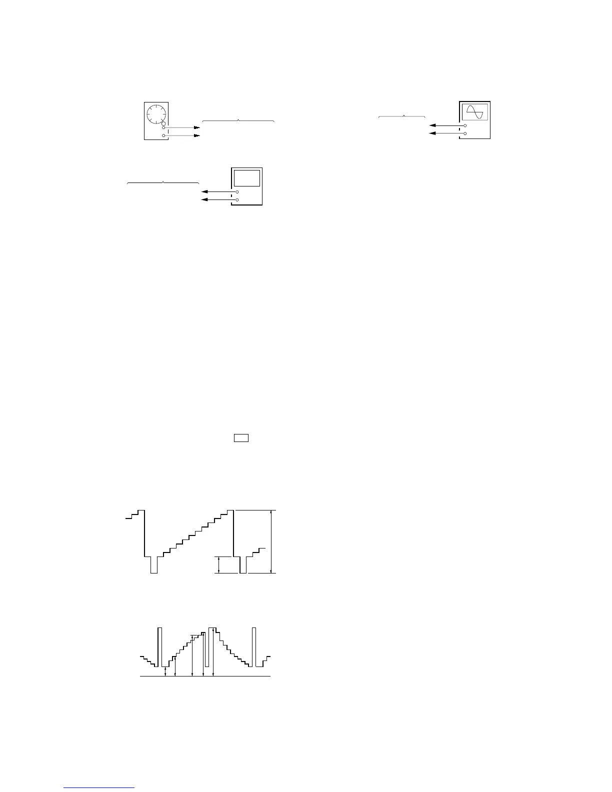
1. Connect an oscilloscope to the TP907 and TP929 (GND) on
the MONITOR board.
2. Press the [SOURCE] button to display “Y Gain”.
3. Adjust by pressing the [VOLUME +]/[VOLUME --] buttons so
that the D value of waveform (fig. 8-2) becomes 3.8 V ±0.1
V.
8. VIDEO ADJUSTMENT
Note: Perform the following adjustment items in test mode.
Common Setting:
1. Press the [POWER] button to turn the power on.
2. Set the signal format system to NTSC. (refer to “SECTION 4.
TEST MODE”)
3. While pressing the [S-MENU] and u buttons, press the
[RESET] button to enter the test mode, and enter the “2. FOR
FACTORY” mode. (refer to “SECTION 4. TEST MODE”)
4. Input 10 steps signal (NTSC, without burst) to the A/V INPUT
jack (J1004 on the MAIN board) from pattern generator.
Waveform of input signal
fig. 8-1
Waveform of output signal
(TP906, TP907, TP908)
fig. 8-2
0.286 V
1 Vp-p
AB C DE
0 V
+
–
oscilloscop
MONITOR board
TP907
TP929 (GND)
7. IR TRANSMITTER CHECK
Setting:
Procedure:
1. Connect an AF oscillator to the TP501 (L) and TP505 (GND),
and input the audio signal (400 Hz, –20 dB).
2. Connect a frequency counter to the TP503 (L) and TP505
(GND) on the MONITOR board.
3. Press the [POWER] button to turn the power on.
4. Press the [S-MENU] button nine times to display “IR
HEADPHONE”, and press the [VOLUME +] button to select
“ON”.
5. Check that the value of frequency counter is 2.3 MHz ±45
kHz.
6. In the same manner, check that the frequency of R-CH is 2.8
MHz ±45 kHz.
AF oscillator
400 Hz, –20 dB
TP501 (L), TP502 (R)
MONITOR board
TP505 (GND)
+
–
frequency counter
MONITOR board
TP503 (L), TP504 (R)
TP505 (GND)
2 Black Limiter Level
Procedure:
1. In the “1 Contrast Level of Luminance Signal” status, press
the [SOURCE] button to display “Black Limit”.
2. Adjust by pressing the [VOLUME +]/[VOLUME --] buttons so
that the A value of waveform (fig. 8-2) becomes 1.05 V ±0.15
V.
3 White Limiter Level
Procedure:
1. In the “2 Black Limiter Level” status, press the [SOURCE]
button to display “White Limit”.
2. Adjust by pressing the [VOLUME +]/[VOLUME --] buttons so
that the E value of waveform (fig. 8-2) becomes 3.95 V ±0.15
V.
4 R-sub Bright
Procedure:
1. In the “3 White Limiter Level” status, connect the
oscilloscope to the TP906 and TP929 (GND) on the
MONITOR board.
2. Press the [SOURCE] button to display “R-Sub BRT”.
3. Adjust by pressing the [VOLUME +]/[VOLUME --] buttons so
that the A value of waveform (fig. 8-2) becomes 1.05 V ±0.15
V.
5 B-sub Bright
Procedure:
1. In the “4 R-sub Bright” status, connect the oscilloscope to
the TP908 and TP929 (GND) on the MONITOR board.
2. Press the [SOURCE] button to display “B-Sub BRT”.
3. Adjust by pressing the [VOLUME +]/[VOLUME --] buttons so
that the A value of waveform (fig. 8-2) becomes 1.0 V
–
+
0
0
.
.
2
1
V
V
.
6 R-ch Sub Contrast
Procedure:
1. In the “5 B-sub Bright” status, connect the oscilloscope to
the TP906 and TP929 (GND) on the MONITOR board.
2. Press the [SOURCE] button to display “R-Sub CONT”.
3. Adjust by pressing the [VOLUME +]/[VOLUME --] buttons so
that the D value of waveform (fig. 8-2) becomes 3.8 V ±0.1
V.
7 B-ch Sub Contrast
Procedure:
1. In the “6 R-ch Sub Contrast” status, connect the oscilloscope
to the TP908 and TP929 (GND) on the MONITOR board.
2. Press the [SOURCE] button to display “B-Sub CONT”.
3. Adjust by pressing the [VOLUME +]/[VOLUME --] buttons so
that the D value of waveform (fig. 8-2) becomes 3.8 V ±0.1
V.
 Loading...